Location specific in-vehicle frequency tuning data

a technology for location and frequency tuning, applied in the field of providing signal tuning information, can solve problems such as difficulty for listeners operating vehicles outside of home listening areas

Inactive Publication Date: 2011-08-09
TRIMBLE NAVIGATION LTD
View PDF26 Cites 19 Cited by
  • Summary
  • Abstract
  • Description
  • Claims
  • Application Information

AI Technical Summary

Problems solved by technology

Since the number of available preselected tuning frequencies is typically limited, when a motor vehicle is moved outside the signal reception areas of the broadcast stations whose frequencies have been preselected by the listener, the listener must then manually select broadcast signal frequencies for new signal reception areas.
It is often difficult for a listener operating a vehicle outside of a home listening area (e.g., area 12) to discover one or more commercial radio stations that broadcast subject matter in which the listener is interested.

Method used


Image

  • Location specific in-vehicle frequency tuning data
  • Location specific in-vehicle frequency tuning data
  • Location specific in-vehicle frequency tuning data

Examples


Embodiment Construction

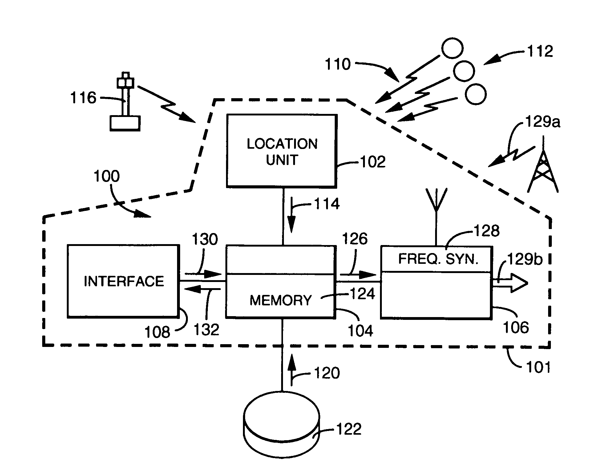
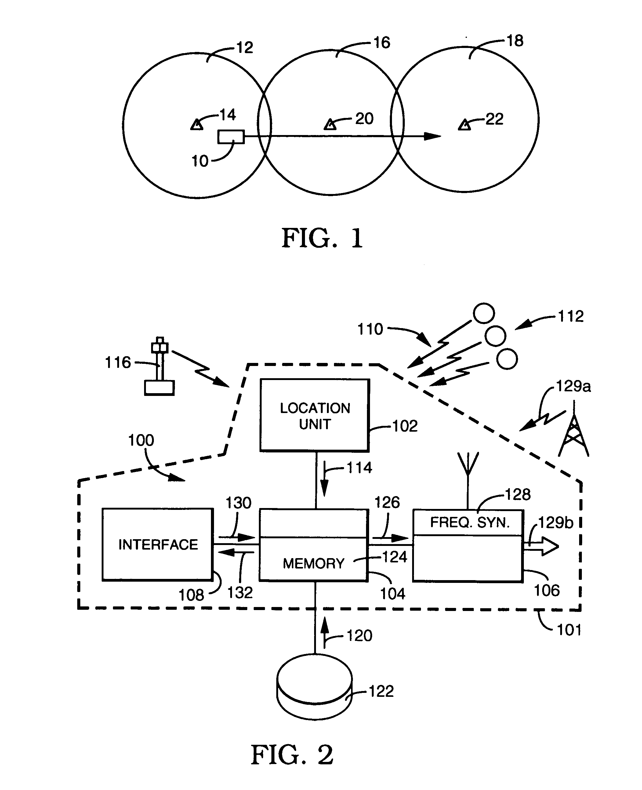
[0011]FIG. 2 is a functional block diagram of an embodiment of the invention. As depicted in FIG. 2, receiving system 100 is positioned in a motor vehicle, represented by dashed line 101. System 100 includes location unit 102, frequency selection unit 104, receiving unit 106, and listener interface 108.

[0012]In some embodiments location unit 102 is a conventional global positioning system (GPS) receiver that receives signals 110 from satellites in GPS constellation 112. Signals 110 include pseudo-range information that location unit 102 uses to conventionally determine the geographic position of system 100. Information 114 identifying system 100's position is output from location unit 102 to frequency selection unit 104. In other embodiments location unit 102 determines geographic position by using corrected GPS information received from local GPS correction stations (not shown). U.S. Pat. No. 5,959,577 discloses the use of GPS correction stations and is incorporated herein by refer...


PUM


Abstract

An in-vehicle system comprises a location unit, a frequency selection unit, and a receiving unit. Frequency tuning data is loaded into the selection unit. The frequency tuning data includes a radio signal reception area for each unique frequency in the tuning data. The location unit determines the system location and passes the location information to the frequency selection unit. The selection unit selects tuning data for a particular frequency having a signal reception area that encompasses the present vehicle location, and passes the selected data to the receiving unit. The receiving unit uses the selected tuning data to tune the radio signal.

Description

BACKGROUND[0001]1. Field of the Invention[0002]Embodiments pertain to in-vehicle radio frequency signal reception, and more particularly to providing signal tuning information for signal reception areas in which the vehicle is located.[0003]2. Related Art[0004]Many motor vehicles (e.g., automobiles, trucks) are equipped with radio receivers that receive radio signals from commercial radio broadcast stations (e.g., AM, FM). These radio receivers are typically equipped with means (e.g., conventional pushbuttons located on the receiver's front panel) that allow a radio listener to select one of several preselected radio frequencies for tuning and listening to content carried by the signal. At a particular geographic position, therefore, the listener may choose among several preselected commercial radio broadcast stations whose radio signal reception areas encompass the receiver's position. FIG. 1 illustrates motor vehicle 10 operating within reception area 12 of a signal broadcast by c...

Claims


Application Information

Patent Timeline
Patent Type & Authority Patents(United States)
IPC IPC(8): H04W24/00H04M3/42H04L29/06H04L29/08G01S19/14H03J1/00H03J5/02H04B1/38
CPCG01S19/14H03J1/0008H03J5/02H04B1/3805H03J2200/12
Inventor FAN, RODRIC C.
Owner TRIMBLE NAVIGATION LTD
Why Eureka
Try Eureka