LED tube reusable end cap

a technology of end caps and tubes, which is applied in the direction of point-like light sources, semiconductor devices for light sources, lighting and heating apparatus, etc., can solve the problems of art not disclosing the existence of tubes with removable and reusable end caps, and achieve the effect of easy removal and replacemen

Inactive Publication Date: 2011-08-16
ALTERNATIVE CONSUMPTION TECH
View PDF21 Cites 127 Cited by
  • Summary
  • Abstract
  • Description
  • Claims
  • Application Information

AI Technical Summary

Benefits of technology

A further objective is to provide an end cap on a tubular lighting fixture wherein the end cap has clearance holes for receiving contact pins of the fixture so that the end cap may be easily removed from the fixture and replaced on the fixture.

Problems solved by technology

However, the prior art fails to disclose a tube with a removable and reusable end cap.

Method used


Image

  • LED tube reusable end cap
  • LED tube reusable end cap
  • LED tube reusable end cap

Examples


Embodiment Construction

The above described drawing figures illustrate the described apparatus and its method of use in at least one of its preferred, best mode embodiment, which is further defined in detail in the following description. Those having ordinary skill in the art may be able to make alterations and modifications to what is described herein without departing from its spirit and scope. Therefore, it should be understood that what is illustrated is set forth only for the purposes of example and should not be taken as a limitation on the scope of the present apparatus and its method of use.

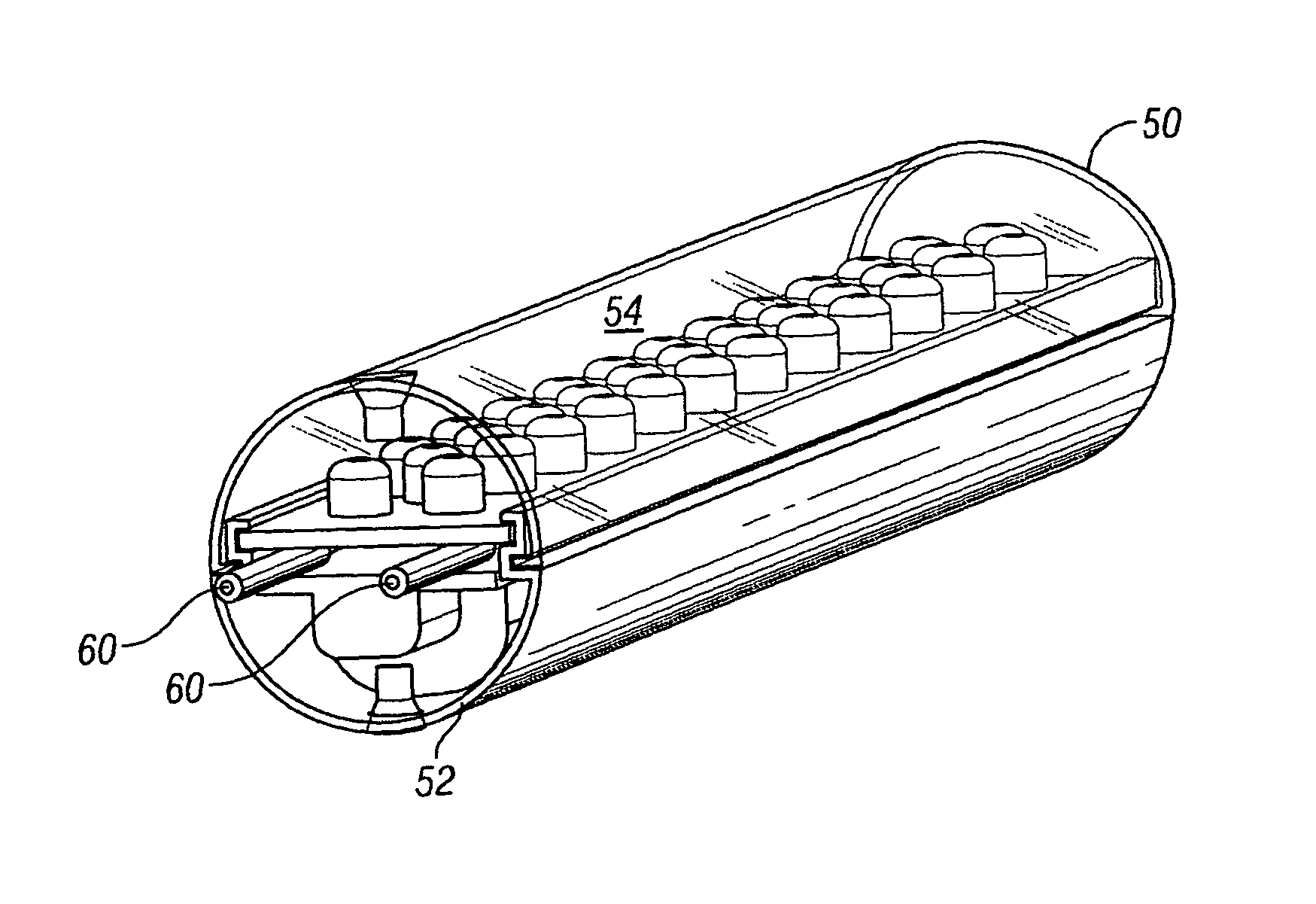
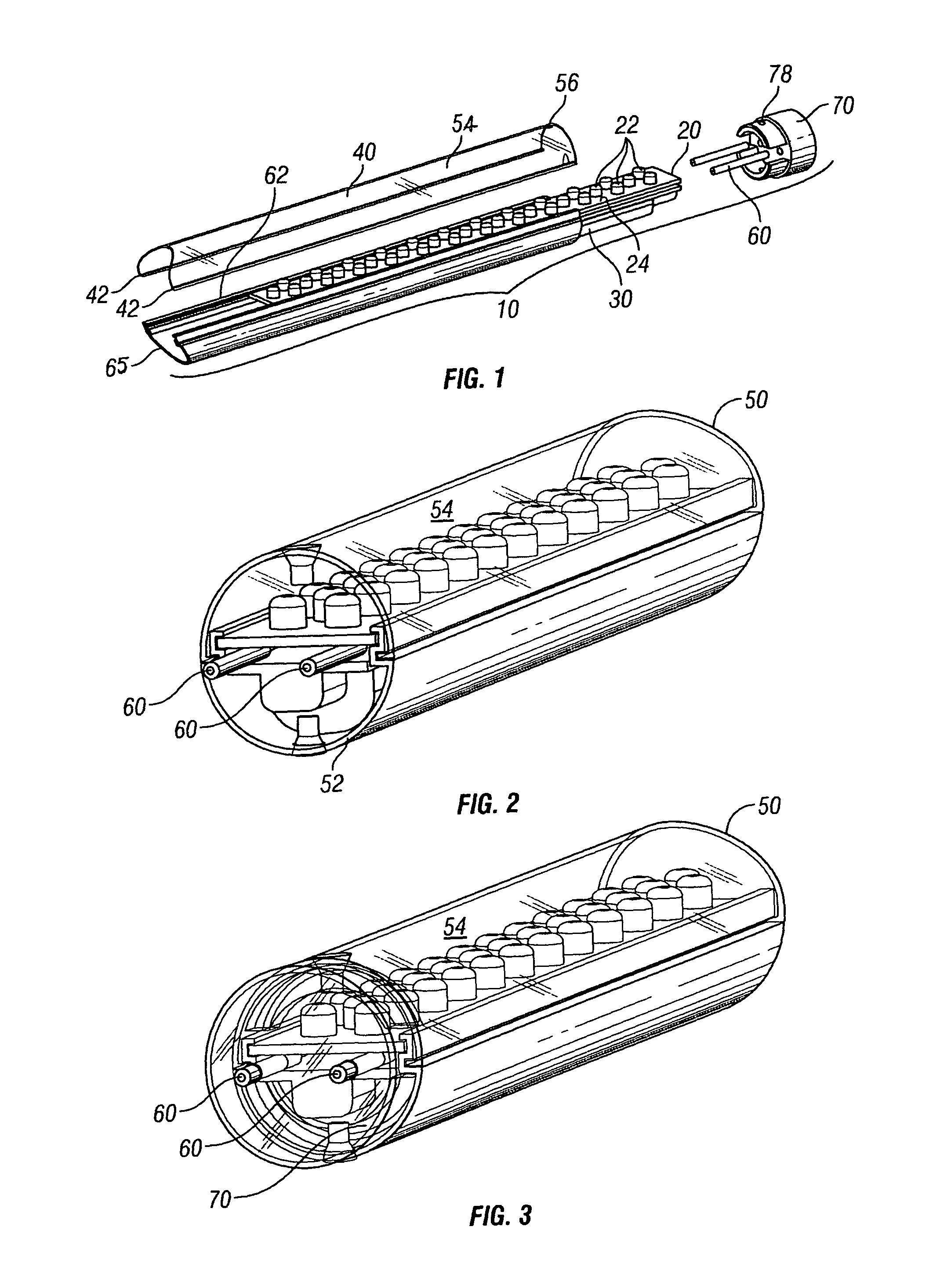
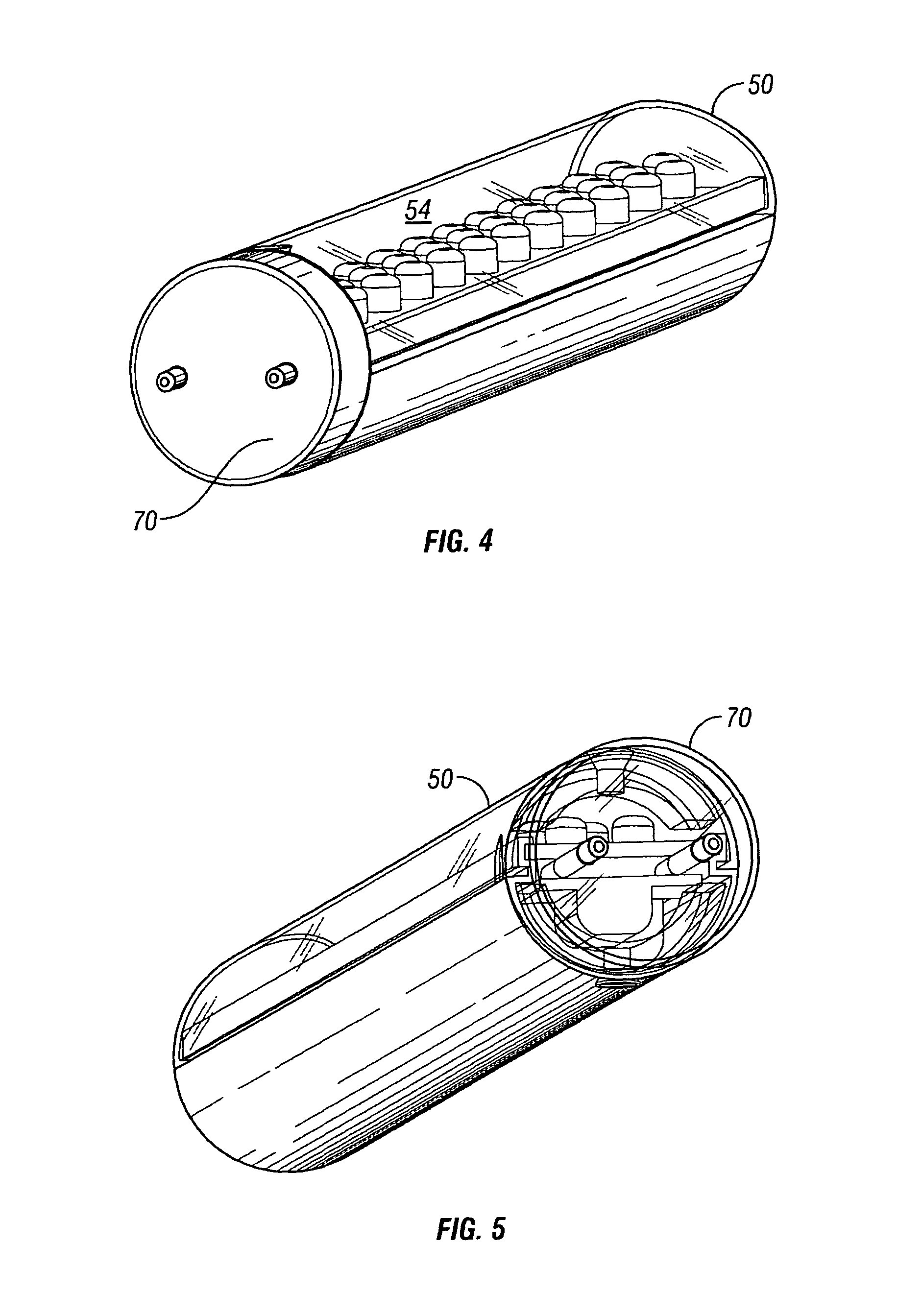
Shown in the separated view of FIG. 1 is a light emitting diode (LED) lighting tube assembly 10 made up of individual parts including a circuit board 20 with a plurality of LEDs 22 mounted on its top surface 24. The LEDs 22 are components of an electrical circuit which includes a power converter 30, of any common and well known type, located adjacent to a bottom side 26 (FIG. 6) of the circuit board 20, the powe...


PUM


Abstract

A replacement for the standard fluorescent lamp tube has a plurality of LED devices mounted on a circuit board. The enclosure within which the circuit board is held has a clear or frosted lens mounted on a heat sink. The lens and heat sink each are arcuately shaped and together form a circular tube. A power converter is mounted below the circuit board and transfers its heat to the heat sink. A pair of pins mounted on the power converter extend beyond one end of the tube. An end cap has means for snapping onto and off the end of the tube and has clearance holes for the pins to protrude through and extend beyond so as to be fitting into mechanical and electrical contact with a standard lamp mounting fixture.

Description

CROSS-REFERENCE TO RELATED APPLICATIONSNot applicable.STATEMENT REGARDING FEDERALLY SPONSORED RESEARCH OR DEVELOPMENTNot applicable.THE NAMES OF THE PARTIES TO A JOINT RESEARCH AGREEMENTNot applicable.INCORPORATION-BY-REFERENCE OF MATERIAL SUBMITTED ON A COMPACT DISCNot applicable.REFERENCE TO A “MICROFICHE APPENDIX”Not applicable.SEQUENCE LISTINGNot applicable.BACKGROUND OF THE INVENTION1. Field of the Present DisclosureThis disclosure relates generally to tubular lighting devices such as fluorescent lamps, and more particular to a replacement for fluorescent lamps having LED illumination and a replaceable and reusable end cap.2. Description of Related Art including information disclosed under 37 CFR 1.97 and 1.98Sun et al., US 2008 / 0158870 discloses that a Light Emitting Diode (LED) light tube is applied to be directly inserted into two pairs of electrode insertion holes of a fluorescent light tube fixture to replace a fluorescent tube. The LED light tube comprises a heat-dissipat...

Claims


Application Information

Patent Timeline
Patent Type & Authority Patents(United States)
IPC IPC(8): F21V3/00F21V5/00
CPCF21K9/17F21Y2101/02F21Y2103/003F21Y2103/10F21Y2115/10F21K9/272
Inventor MEURER, WILLIAM HENRY
Owner ALTERNATIVE CONSUMPTION TECH
Why Eureka
Try Eureka