Light guide apparatus of backlight module

a technology of backlight module and light guide plate, which is applied in the direction of lighting and heating apparatus, instruments, optical elements, etc., can solve the problems of high fabrication cost, non-uniform illumination condition of light guide plate, and relatively complex fabrication process

Active Publication Date: 2011-08-16
GLOBAL LIGHTING TECHNOLOGIES INC
View PDF3 Cites 71 Cited by
  • Summary
  • Abstract
  • Description
  • Claims
  • Application Information

AI Technical Summary

Benefits of technology

[0008]A primary objective of the present invention is to provide a solution to the problem of the conventional backlight module, in which the fabrication process of providing the LEDs serving as light sources to the light guide plate is complex and costly.
[0009]According to the present invention, the backlight module includes a plurality of LEDs, a circuit, and a light guide plate. The circuit is adapted for controlling the light source of the backlight module and is directly configured on the light guide plate, and then the LEDs are directly welded to circuit contacts of the circuit that are distributed at one side of the light guide plate. In such a way, the process of assembling the LEDs and the light guide plate is simplified.
[0011]According to another embodiment of the present invention, the light guide plate is configured with at least one recess at a lateral side for providing a light source. The contacts of the circuit are arranged at both sides of the recess or even inside the recess, and the LED is also received inside the recess. The electrical contacts of the LED are then welded to the contacts of the circuit. In such a way, the backlight module can achieve a further minimized size.

Problems solved by technology

This often causes a nonuniform illuminating condition of the light guide plate.
As such, the process of the fabrication is relatively complex, and needs a high fabrication cost.

Method used


Image

  • Light guide apparatus of backlight module
  • Light guide apparatus of backlight module
  • Light guide apparatus of backlight module

Examples


Embodiment Construction

[0019]The accompanying drawings are included to provide a further understanding of the invention, and are incorporated in and constitute a part of this specification. The drawings illustrate embodiments of the invention and, together with the description, serve to explain the principles of the invention.

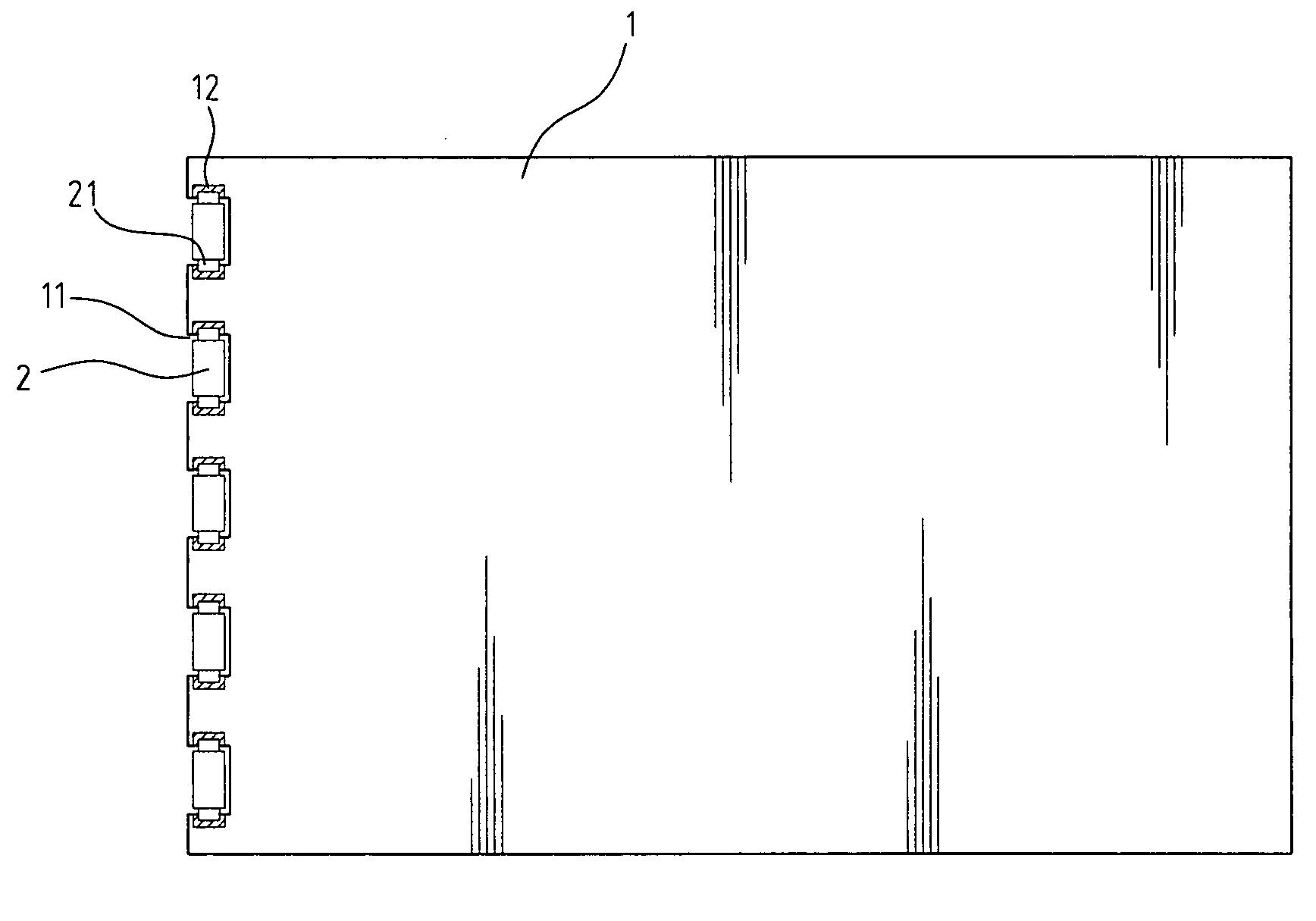
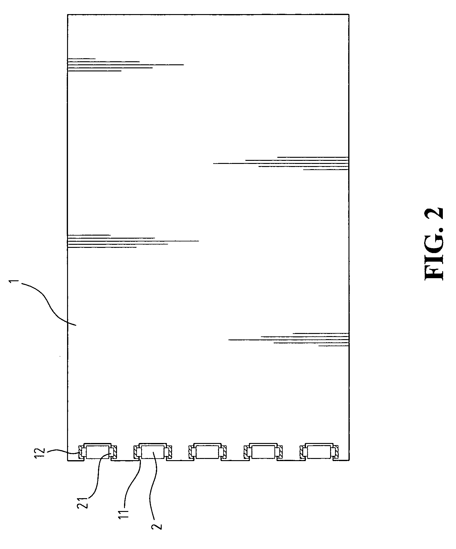
[0020]FIG. 2 is a schematic view showing that the LEDs are directly welded to one lateral side of a light guide plate according to an embodiment of the present invention. Referring to FIG. 2, the present invention provides a light guide apparatus of a backlight module. According to an embodiment of the present invention, the light guide apparatus includes a light guide plate 1, and a plurality of LEDs 2 provided at least one lateral side of the light guide plate 1. The light guide plate 1 includes a plurality of recesses 11 configured at one lateral side of the light guide plate. Each of the recesses 11 includes two circuit contacts 12 distributed at two sides of the recess 11. The l...


PUM


Abstract

A light guide apparatus of a backlight module is provided. The light guide apparatus includes a light guide plate and a plurality of LEDs serving as light sources disposed at one lateral side of the light guide plate. The light guide plate includes a circuit configured thereon, and the light sources are welded on the circuit of the light guide plate.

Description

BACKGROUND OF THE INVENTION[0001]1. Field of the Invention[0002]The present invention relates to a light guide structure including a light guide plate and a light source, and being adapted for a backlight module.[0003]2. The Prior Arts[0004]Backlight modules are now widely used in many kinds of electronic products. For example, displays of notebook computers, mobile phones, and liquid crystal televisions do not emit light by themselves, and require backlight modules for providing light sources.[0005]A typical backlight module includes a light guide plate and a light source. Light emitting diodes (LED) are often employed serving as light sources of backlight modules for those electronic products demanding a relatively thin thickness. With respect to such a backlight module, the LED light source is positioned at a lateral side of the light guide plate. The light guide plate has a first surface and a second surface opposite to the first surface. A reflective sheet is provided at the fi...

Claims


Application Information

Patent Timeline
Patent Type & Authority Patents(United States)
IPC IPC(8): F21V23/00
CPCG02B6/0021G02B6/0068G02B6/0083
Inventor TSAI, CHUNG-LIN
Owner GLOBAL LIGHTING TECHNOLOGIES INC
Why Eureka
Try Eureka