Single-winding multi-stage scroll expander

a scroll expander and single-winding technology, applied in the direction of machines/engines, combination engines, liquid fuel engines, etc., can solve the problems of insufficient durability of the vane-type, difficulty in reducing in size and weight, and partially losing high-pressure gas heat, etc., to achieve simple, small-sized, and increase energy conversion efficiency

Inactive Publication Date: 2005-08-02
ANEST IWATA CORP
View PDF6 Cites 23 Cited by
  • Summary
  • Abstract
  • Description
  • Claims
  • Application Information

AI Technical Summary

Benefits of technology

[0010]It is an object of the present invention to provide a single-winding multi-stage scroll expande

Problems solved by technology

To drive a relatively low-output generator, the turbine-type is weak against water, the screw-type is difficult to reduce in size and weight, and the vane-type is not sufficiently durable.
However, in an actual scroll expander, high-pressure gas heat is partiall

Method used


Image

  • Single-winding multi-stage scroll expander
  • Single-winding multi-stage scroll expander
  • Single-winding multi-stage scroll expander

Examples


Embodiment Construction

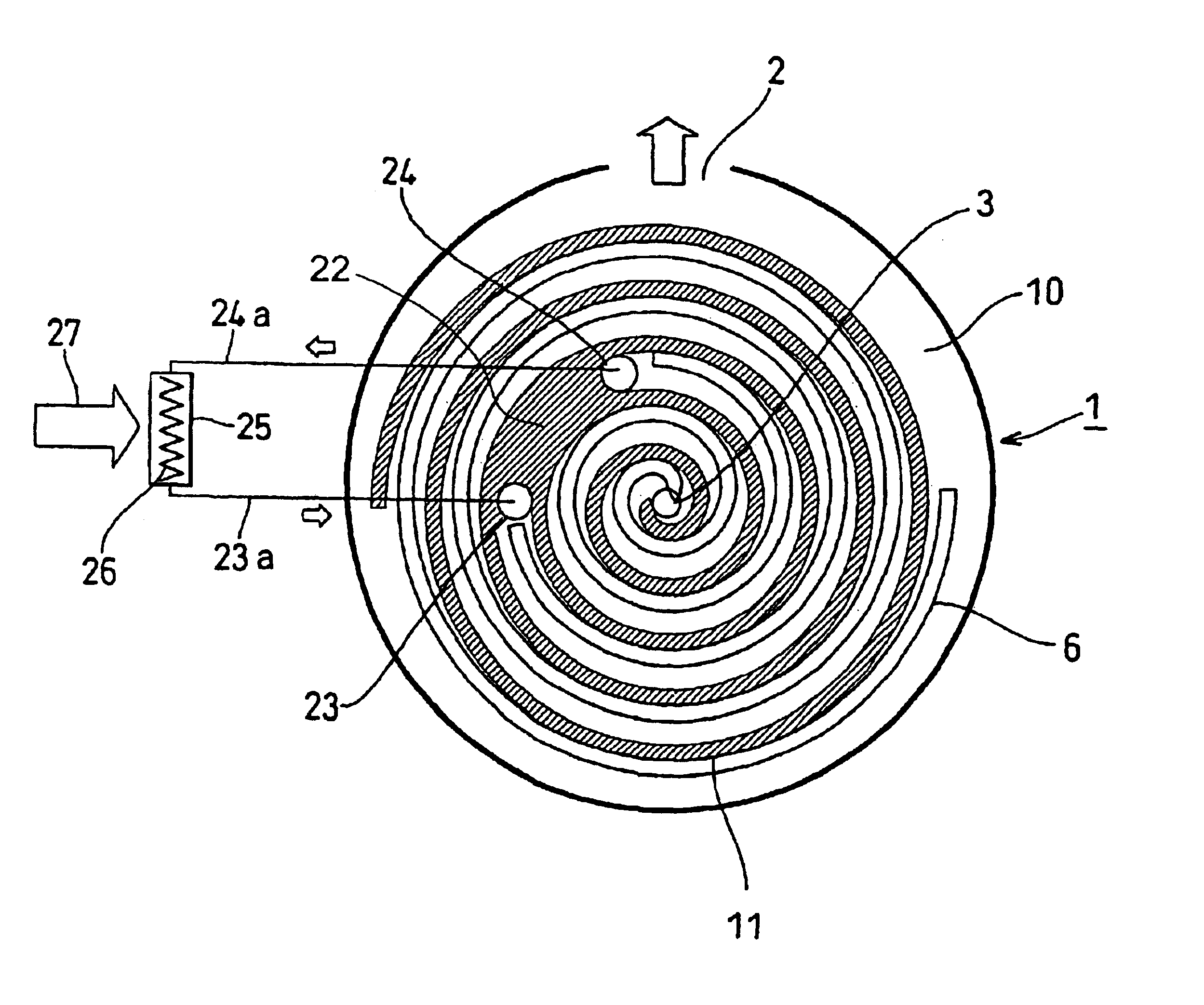
[0014]As known among persons skilled in the art, a scroll expander means an energy converting mechanism for converting heat energy into kinetic energy in which a high-pressure gas such as air or vapor is fed through the center of a wrap of a fixed or orbiting scroll such that expansion of the high-pressure gas in the expander is converted to rotation of a driving shaft integrally formed with a crankshaft to produce electricity.

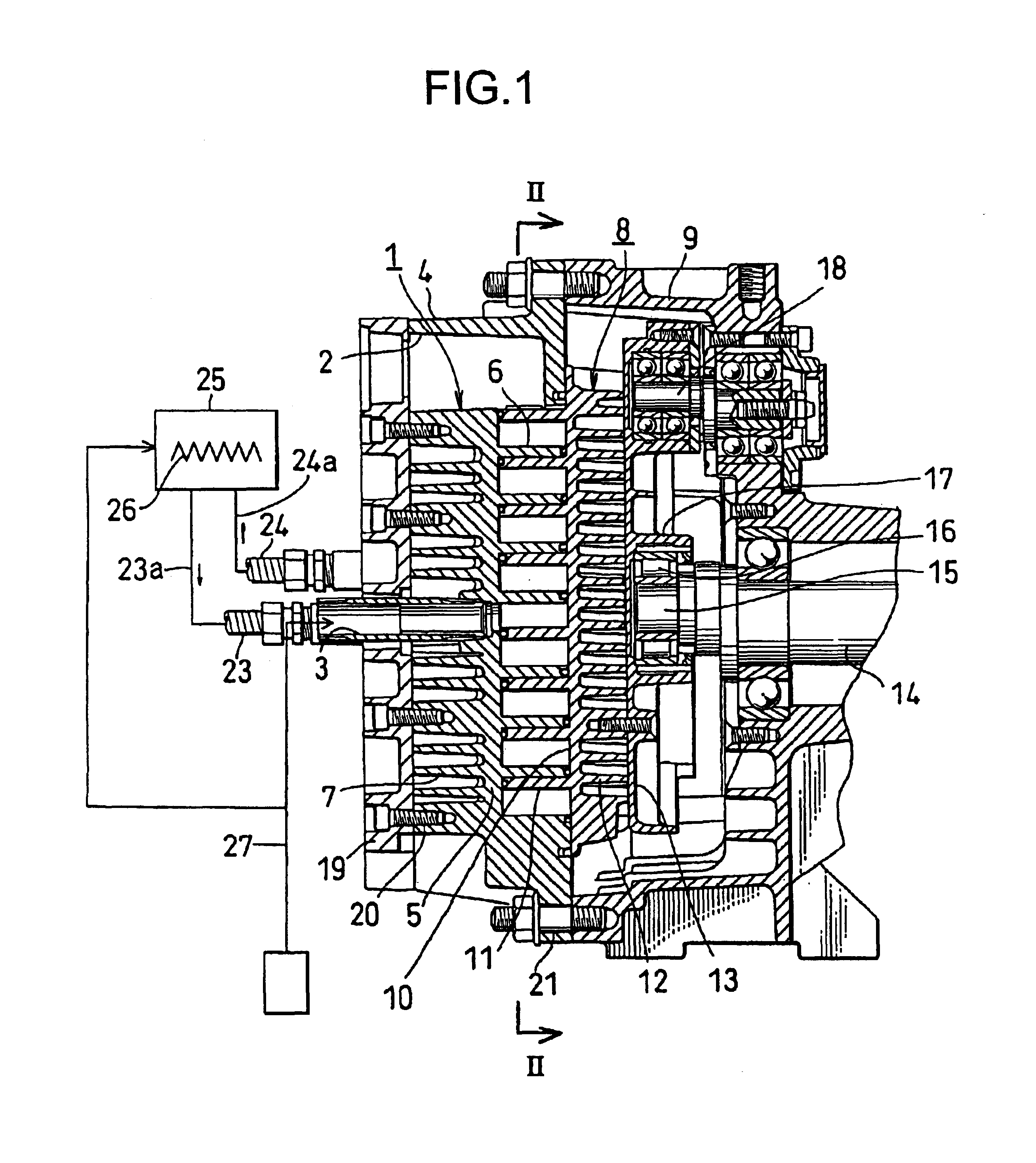
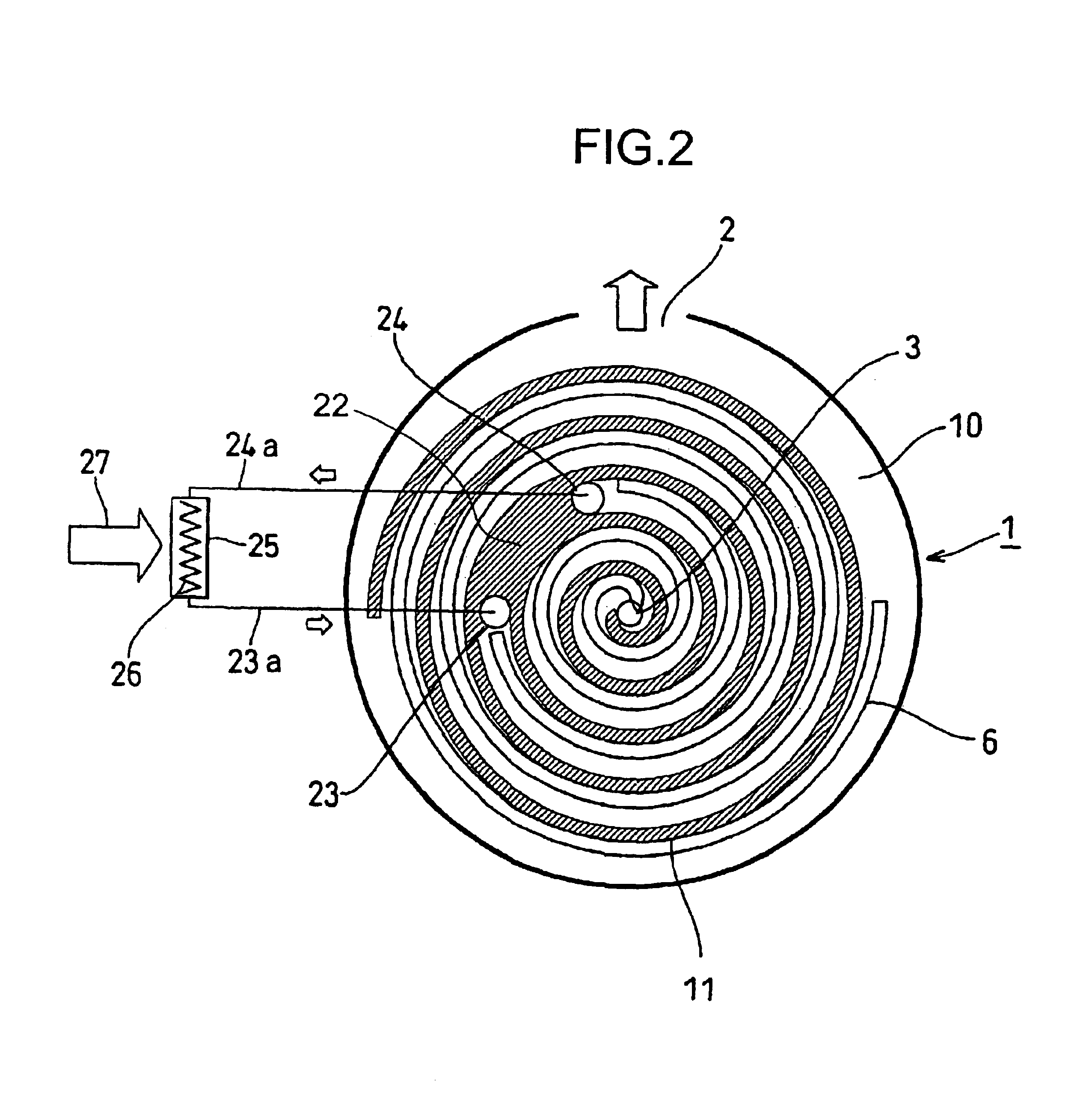
[0015]A single-winding two-stage scroll expander as one example of a multi-stage scroll expander will be described with respect to FIGS. 1 and 2. The present invention may be applied to scroll expanders of more than two stages as well.

[0016]A fixed scroll 1 comprises a fixed scroll housing 4 which has a second-stage outlet 2 on the outer portion and a first-stage inlet 3 at the center; a fixed end plate 5 integrally formed with the housing 4; a spiral fixed wrap 6 on the front surface of the fixed end plate 5; and a plurality of cooling fins 7 having the same ...


PUM


Abstract

A single-winding multi-stage expander comprises a fixed scroll and an orbiting scroll which revolves eccentrically with respect to the fixed scroll so as to pressurize a sealed chamber formed between the two scrolls to drive a crankshaft. A high-temperature pressurized gas is introduced into a first-stage inner division and sent to an external heater. The heated gas is sent back to a second-stage outer division of the expander to significantly increase efficiency thereof.

Description

BACKGROUND OF THE INVENTION[0001]The present invention concerns a single-winding multi-stage scroll expander by which utilizable rotational force is effectively obtained by a wasted high-temperature steam in areas where heating steam is used, such as the Northern part of North America or Northern Europe.[0002]Expanders for driving an electric generator include a turbine-type, a screw-type, a vane-type and a scroll-type.[0003]To drive a relatively low-output generator, the turbine-type is weak against water, the screw-type is difficult to reduce in size and weight, and the vane-type is not sufficiently durable.[0004]The scroll-type is most suitable as a small-sized, light, durable expander, a fact acknowledged among learned engineers.[0005]The simplest scroll expander in structure comprises a single winding. A high-temperature, high-pressure gas such as air or vapor is fed through the center of a wrap. Expansion of the gas in the expander is converted into rotation of a crankshaft to...

Claims


Application Information

Patent Timeline
IPC IPC(8): F01C21/06F01C21/00
CPCF01C21/06
Inventor KIMURA, HIDEYUKIKENMOCHI, YUTAKA
Owner ANEST IWATA CORP
Why Eureka
Try Eureka