Light-Emitting Component with an Arrangement of Electrodes

a technology of light-emitting components and electrodes, which is applied in the direction of electroluminescent light sources, organic semiconductor devices, thermoelectric devices, etc., can solve the problems of increased production costs, disadvantageous commercial use of such lighting components, and complex substrate structure, so as to reduce manufacturing costs, reduce production costs, and simplify the effect of generating light in different colours

Inactive Publication Date: 2006-12-07
NOVALED GMBH
View PDF99 Cites 24 Cited by
  • Summary
  • Abstract
  • Description
  • Claims
  • Application Information

AI Technical Summary

Benefits of technology

[0019] A major advantage which the invention achieves over the state of the art is that the manufacture of components with organic light-emitting substructures for generating light in different colours is significantly simplified. The yield can also be increased. These advantages entail a reduction in manufacturing costs. Electrical contacting is also simplified. Process stages can be waived, saving costs. In particular, unlike the state of the art, the process stage for producing one or more layers of insulation between the electrode and the counter-electrode can be waived.

Problems solved by technology

In addition, the structure of the substrate may be more complex than is the case with common white OLEDs, which emit white light directly.
However, a disadvantage of such OLED-based white light generation is that the use of OLED substructures entails increased production costs compared to other OLED lighting designs, which dispense with additional structuring in the production of OLED illumination.
This is disadvantageous to the commercial use of such lighting components.
However, such an approach requires a connecting step for bonding during manufacture, for example by means of adhesive.

Method used


Image

  • Light-Emitting Component with an Arrangement of Electrodes
  • Light-Emitting Component with an Arrangement of Electrodes
  • Light-Emitting Component with an Arrangement of Electrodes

Examples


Embodiment Construction

OF THE INVENTION

[0034] The invention is explained in more detail below by means of embodiment examples, with reference to the drawings, wherein:

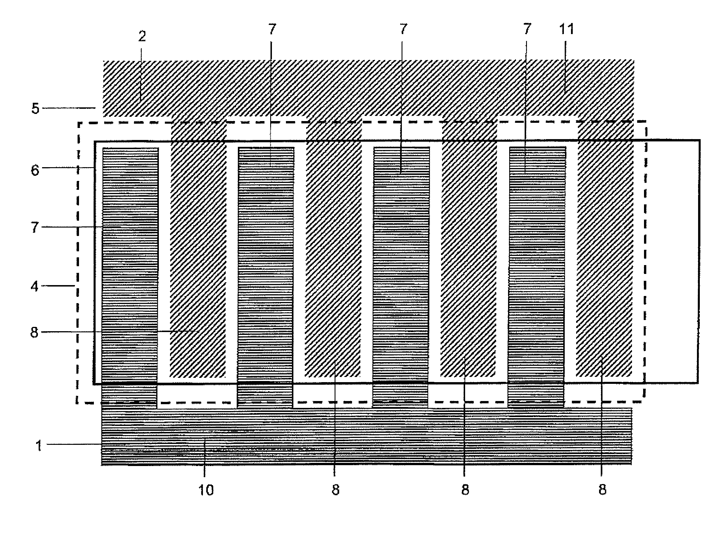
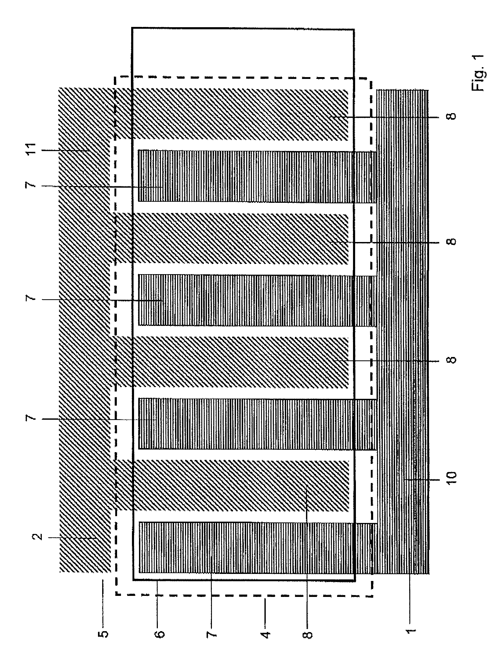
[0035]FIG. 1 is a schematic representation of a light-emitting component with multiple organic areas, which are distributed across a component surface and which each emit light in two different colours when an electrical voltage is applied, where part electrodes of the electrode are formed so that they do not overlap when looking towards the component surface;

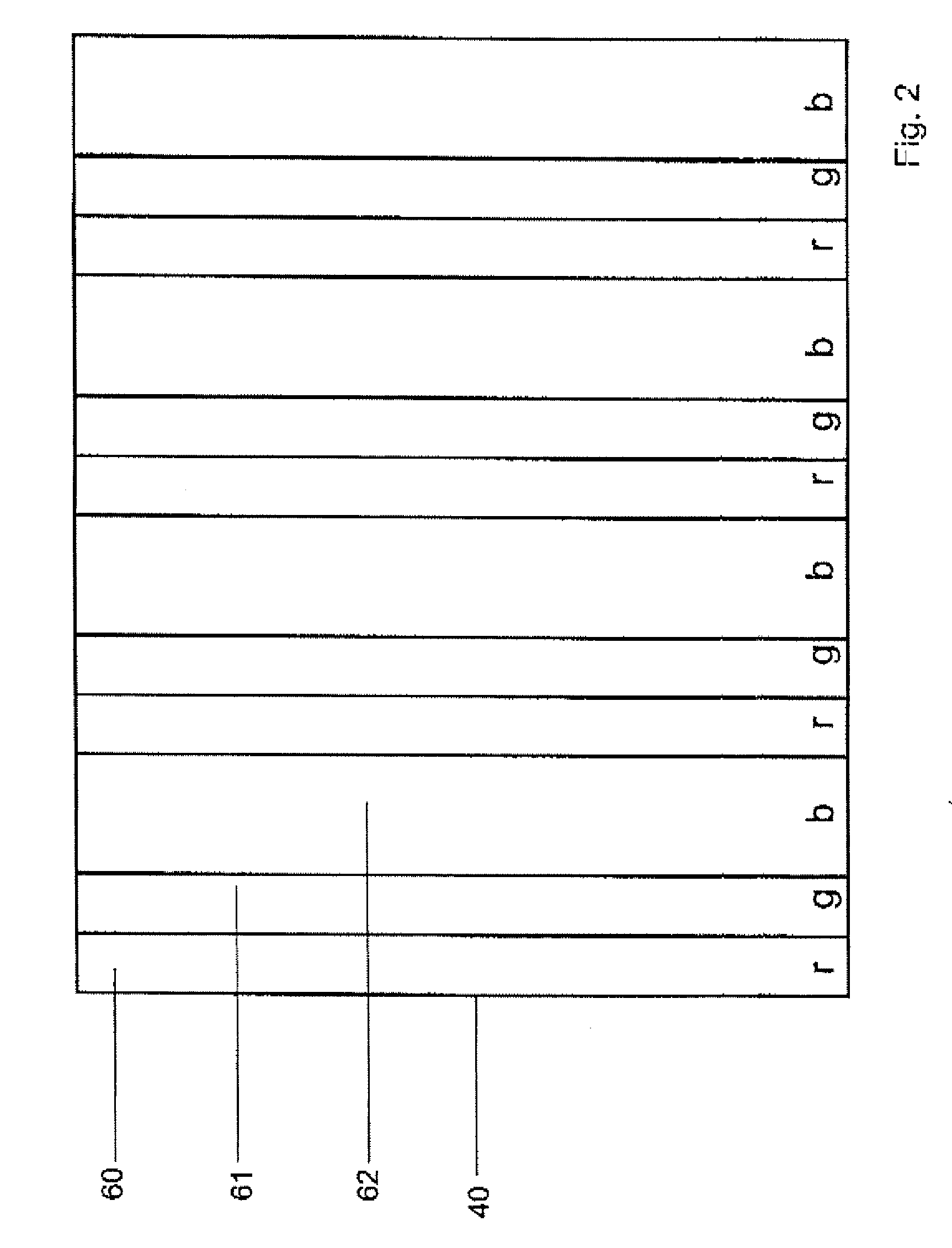
[0036]FIG. 2 is a schematic representation of an arrangement of multiple organic areas for a light-emitting component;

[0037]FIG. 3 is a schematic representation of the arrangement of multiple organic areas according to FIG. 2, where a lower electrode is formed with two non-overlapping part electrodes;

[0038]FIG. 4 is a schematic representation of the arrangement of multiple organic areas according to FIG. 2, where an upper electrode with two non-overlapping part electrodes is formed;...


PUM


Abstract

The invention concerns a light-emitting component with an arrangement of electrodes for applying an electrical voltage to multiple organic areas, which form a light-emitting area, are distributed across a component surface and which each emit light when the electrical voltage is applied, in which the multiple organic areas are arranged between a flat-formed electrode and a flat-formed counter-electrode, where the electrode consists of a part electrode and an additional part electrode, which is electrically isolated from the part electrode and is formed so that it interlocks with it, where the electrode and the counter-electrode are formed so that they do not overlap outside the light-emitting area when looking towards the component surface.

Description

[0001] The invention concerns a light-emitting component with an arrangement of electrodes for applying an electric current to multiple organic areas, which form a light-emitting area, are distributed across a component surface and which each emit light when the electric current is applied, and in which the multiple organic areas are arranged between a flat-formed electrode and a flat-formed counter-electrode. BACKGROUND TO THE INVENTION [0002] Document DE 101 45 492 A1 describes a light-emitting component with a light-emitting organic area, which produces white light by means of OLED (OLED—organic light-emitting diode) substructures, for example, in the form of flat-formed points or strips, which generate white light on different wavelengths, and by means of an adjacent diffuser. The OLED substructures are contacted by using separate electrodes and actuated by means of a voltage source, by which means an optimised mixture of the different colours may be achieved. [0003] A procedure...

Claims


Application Information

Patent Timeline
Patent Type & Authority Applications(United States)
IPC IPC(8): H01L29/08
CPCH01L27/3204H01L2251/564H01L27/3211H10K59/86H10K59/35H10K71/841H05B33/26
Inventor BIRNSTOCK, JANMURANO, SVEN
Owner NOVALED GMBH
Why Eureka
Try Eureka