Modeling Light Transport In Complex Display Systems

a display system and light transport technology, applied in the field of calibrating projectors, can solve the problems of inability to capture images, inapplicable calibration techniques of camera equipment, and real practical limitations of its use, and achieve the effect of simplifying the application of dual photography

Inactive Publication Date: 2007-07-26
SEIKO EPSON CORP
View PDF16 Cites 26 Cited by
  • Summary
  • Abstract
  • Description
  • Claims
  • Application Information

AI Technical Summary

Benefits of technology

[0023]It is another object of the present invention to simplify the use of dual photography in the calibration of a real projector in projector-camera systems.
[0024]It is a further object of the present invention to make use of the benefits of dual photography in the calibration of a real projector while avoiding the need of some of the more time consuming and complicated requirements of dual photography.SUMMARY OF THE INVENTION
[0025]The above objects are met in a system that simplifies the generation of dual transport matrix T, simplifies the implementation of light transport coefficients in dual photography, and combines the ease of dual photography manipulation with the reduced calculation requirement of nomography.
[0026]Application of dual photography is simplified by reducing the number of captured images needed to generate a light transport matrix T of (p×q) projection pixel array from (p×q) images to (p+q) images. Manipulation of the light transport matrix is simplified by replacing the use of a matrix T with an index associating each projection pixel to only non-zero light transport values. By eliminating the use of zero-valued light transport coefficients, the memory and processing requirements for implementing dual photography are greatly reduced. This dual photography technique is applied to the calibration of projector-camera systems.
[0039]If the first projector is front projector and the second projector is an immersive projector, then the immersive projector can be used to recreate a front projected image from the point of view of an audience without worrying about the audience blocking the projection path of a front projector.

Problems solved by technology

A key problem that builders of projector-camera systems and devices need to solve is the determination of the internal imaging parameters of each device (the intrinsic parameters) and the determination of the geometric relationship between all projectors and cameras in the system (the extrinsic parameters).
However, since all camera calibration techniques require that the camera (i.e. the imaging device being calibrated) capture a number of images, it would appear that camera calibration techniques cannot readily be applied to projectors, which cannot capture images.
While this bootstrapping technique is a tested-and-proven calibration method for projector-camera systems, it is not applicable to the calibration of self-contained projector-camera devices, since it requires the use of external stereo camera pairs.
Since a digital projector and a digital camera can both have millions of pixels each, the acquisition, storage, and manipulation of multitudes of light transport coefficients can place real practical limitations on its use.
Thus, although in theory dual photography would appear to offer great benefits, in practice, dual photography is severely limited by its physical and impractical requirements of needing extremely large amounts of computer memory (both archive disk-type memory and active silicon memory) and needing extensive and fast computational processing.

Method used


Image

  • Modeling Light Transport In Complex Display Systems
  • Modeling Light Transport In Complex Display Systems
  • Modeling Light Transport In Complex Display Systems

Examples


Embodiment Construction

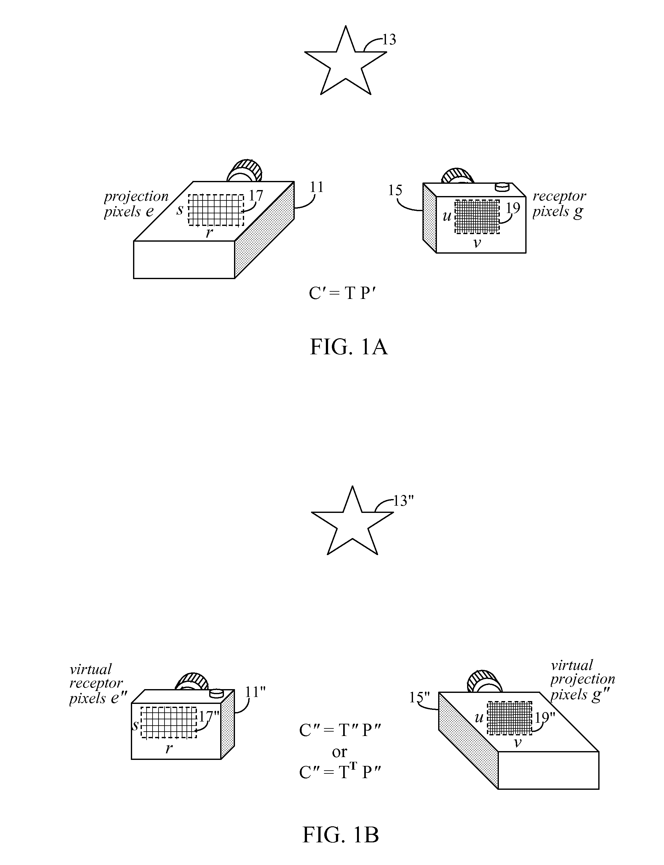
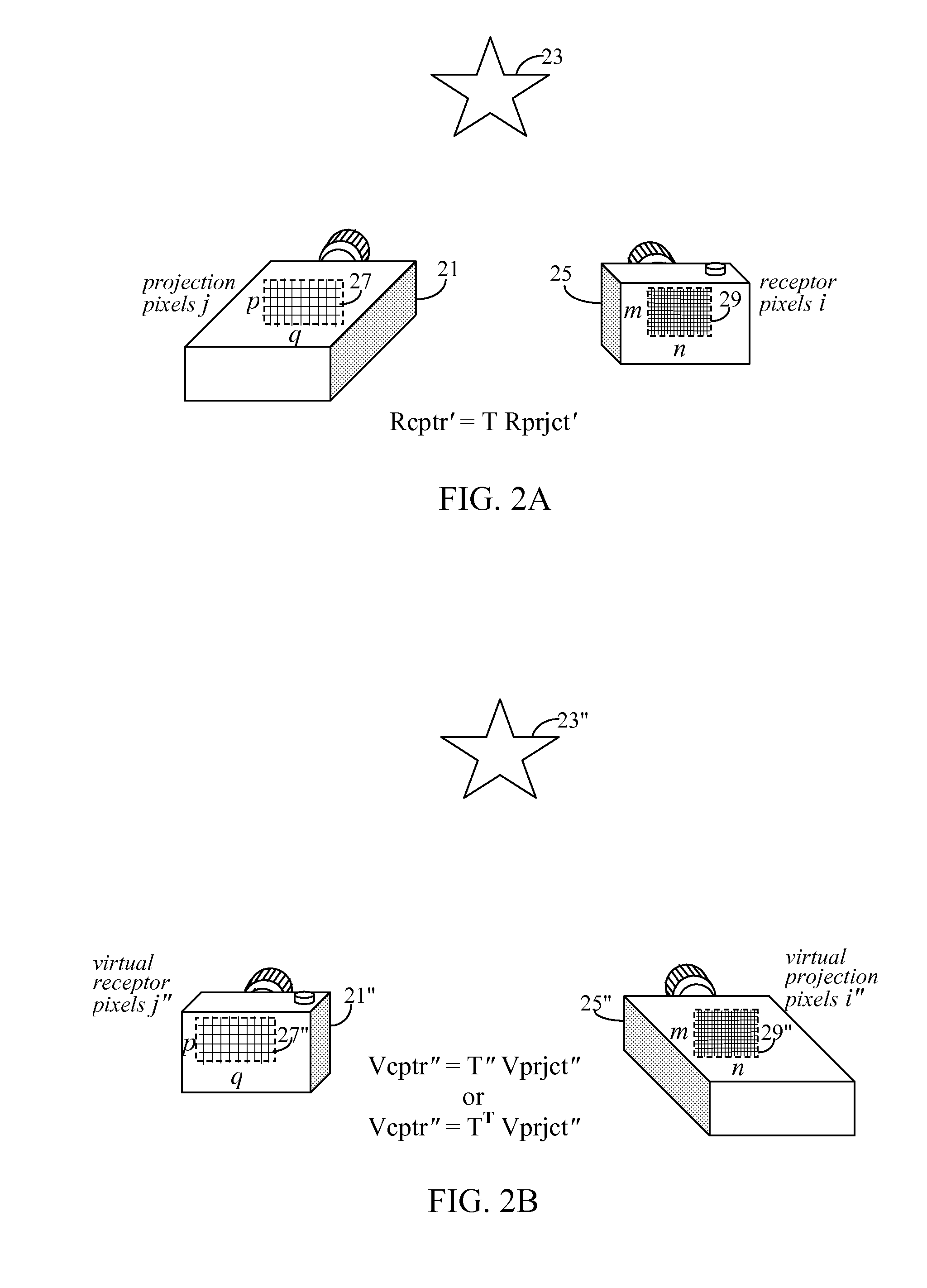
[0077]If projectors could capture images, then there would be no need to differentiate between real projectors and real cameras, and projector-camera systems could be treated like multi-camera systems. Subsequently, the standard camera calibration techniques described above could be used to calibrate projector-camera systems. In other words, if the projector could be treated as a pseudo-camera, then it could be calibrated along with a real camera in a manner similar to the camera calibration stage of the multi-camera system described above, and the “bootstrapping” projector calibration stage might be eliminated.

[0078]Consequently, whereas in the “bootstrapping” projection calibration technique, a projector would project known feature points to be captured by a stereo pair of pre-calibrated cameras onto a known projection surface to determine the contours of the projection surface, a dual photography technique could eliminates the need for the stereo pair pre-calibrated cameras.

[0079...


PUM


Abstract

An image created by a first projector is recreated using a second projector by relating the two projectors to a common point of view, preferably as viewed from a camera. A first transport matrix T1 is captured to relate the first projector to the camera. A second transport matrix T2 is then capture to relate the second projector to the camera. To have a first image p1, as projected by the first projector, reproduced by the second projector, the second projector projects a distorted image defined as (T2−1)(T1)p1. The inverse of T2, as used in this equation is an estimation defined by first creating an intermediate matrix {hacek over (T)} of equal size as T2. If a column in T2 is denoted as Tr and a corresponding column in {hacek over (T)} is denoted as {hacek over (T)}r, then the construction and population of {hacek over (T)} is defined as {hacek over (T)}r=Tr / (∥Tr∥)2, and the inverse of T2 is estimated as the transpose of {hacek over (T)}.

Description

CONTINUING APPLICATION DATA[0001]This application claims the benefit of U.S. Provisional Application No. 60 / 762,178 filed Jan. 24, 2006 under 35 U.S.C. §119(e), and claims the benefit under Title 35, U.S.C. §120 of application Ser. No. 11 / 613,129, filed Dec. 19, 2006, pending.BACKGROUND OF THE INVENTION[0002]1. Field of the Invention[0003]The present invention is related to methods of calibrating projectors in projector-camera systems, and more specifically related to methods of simplifying application of dual photography.[0004]2. Description of the Related Art[0005]When projectors and cameras are combined, hybrid devices and systems that are capable of both projecting and capturing light are born. This emerging class of imaging devices and systems are known in the research community as projector-camera systems. Typically, the images captured by one or more cameras, is used to estimate attributes about the display environment, such as the geometric shape of the projection surfaces. ...

Claims


Application Information

Patent Timeline
Patent Type & Authority Applications(United States)
IPC IPC(8): G06K9/32G03B21/14G03B21/00
CPCG03B21/26H04N9/3185H04N17/002H04N9/3197H04N9/3194
Inventor TAN, KAR-HANXIAO, JINGBHATTACHARJYA, ANOOP K.
Owner SEIKO EPSON CORP
Why Eureka
Try Eureka