Low-thrust cryogenic propulsion module

a cryogenic propulsion module and low-thrust technology, applied in the field of satellite launch, can solve the problems of difficulty in obtaining, difficulty in adjusting attitude, and difficulty in determining the size of the liquid hydrogen tank 3, and achieve the effect of light weight, simple structure and compact structur

Inactive Publication Date: 2003-06-24
SN DETUDE & DE CONSTR DE MOTEURS DAVIATION S N E C M A
View PDF12 Cites 21 Cited by
  • Summary
  • Abstract
  • Description
  • Claims
  • Application Information

AI Technical Summary

Benefits of technology

The invention seeks to remedy the above-mentioned drawbacks and in particular to enable the orbit of a satellite to be transferred using a device that is simpler, lighter, and more compact than prior art devices while avoiding the use of turbopumps and making it possible to use both thrusters and propellant tanks of reasonable size reducing the bulk of the propulsion stage in question required for transferring the orbit of the satellite.

Problems solved by technology

Nevertheless, that configuration presents various drawbacks.
In particular, in order to reach a temperature of 2000 K, it is necessary to use a solar flux concentration factor of 5000 to 8000, which requires a mirror of very good quality, which is very difficult to obtain when subject to constraints limiting on-board mass.
In addition, pointing towards the sun must be very accurate, of the order of .+-.5 minutes of arc about two axes, which gives rise to problems in attitude control.
The size of the liquid hydrogen tank 3 also constitutes a difficulty.
Developments in orbit transfer systems based on a solar thermal stage are in serious difficulty due to those drawbacks.
Cryogenic stages currently in use nevertheless require turbopumps to be used, and that increases their cost.
Certain authors have proposed making cryogenic stages that are fed by means of pressure, without using turbopumps, but those concepts have not given rise to concrete implementations.
It follows that the mass of helium required for pressurization purposes becomes prohibitive.

Method used


Image

  • Low-thrust cryogenic propulsion module
  • Low-thrust cryogenic propulsion module
  • Low-thrust cryogenic propulsion module

Examples


Embodiment Construction

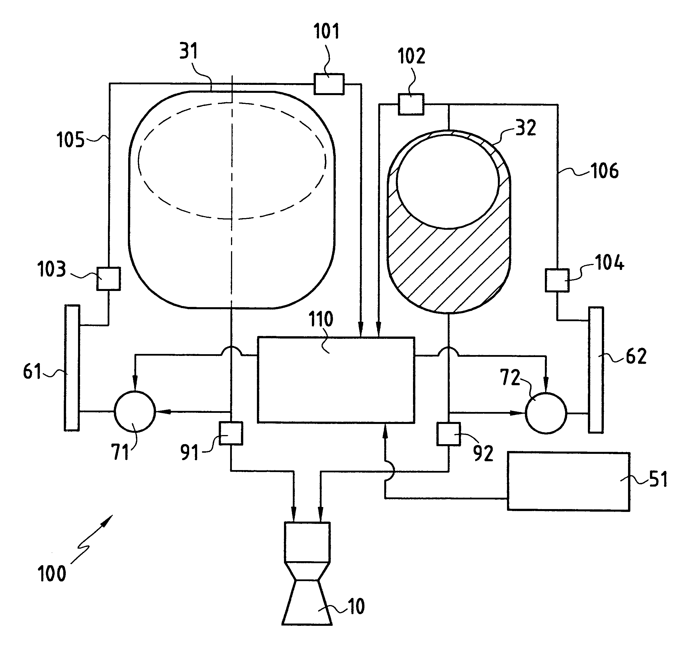
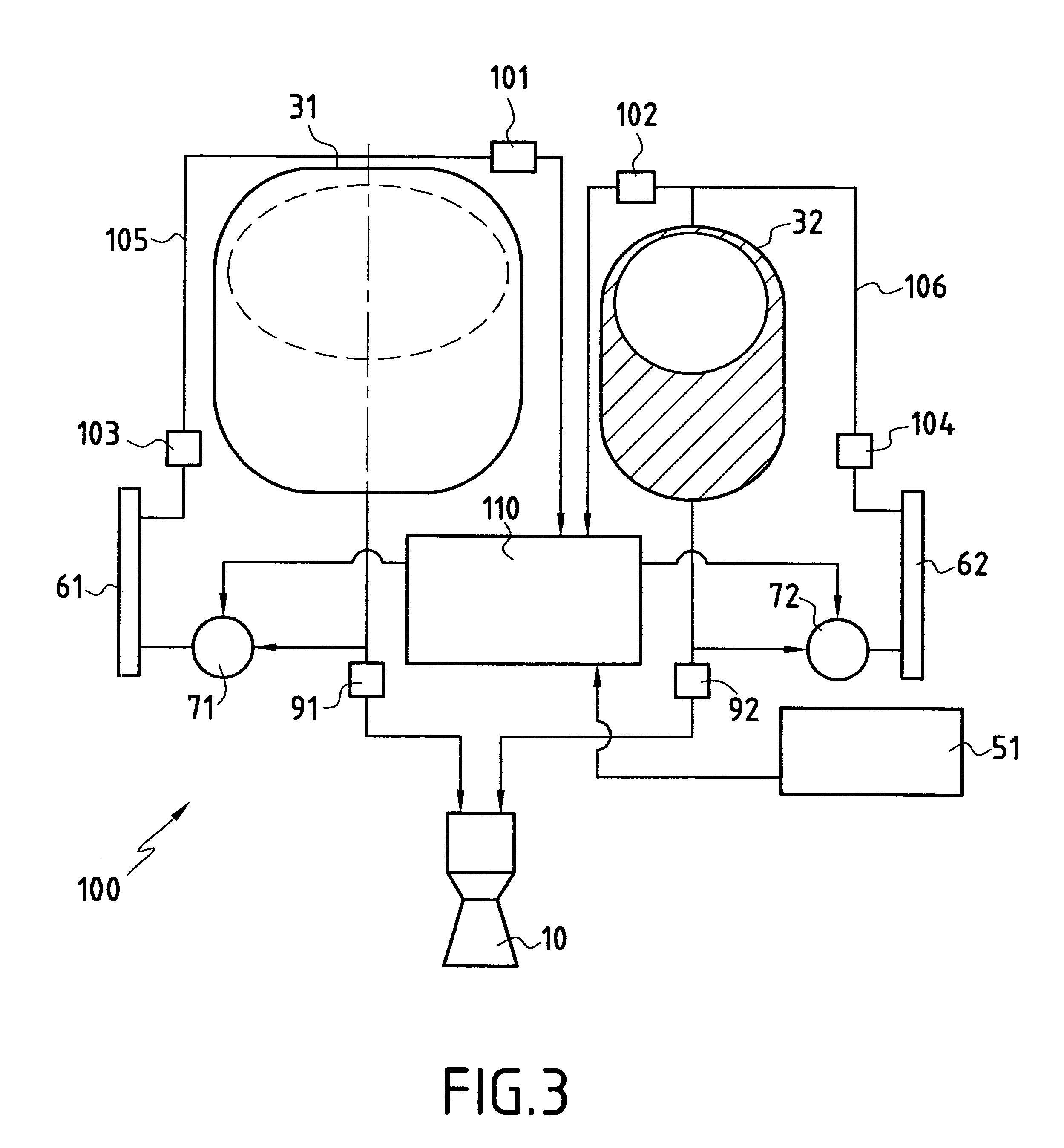
FIG. 1 is an overall diagram showing an example of a cryogenic propulsion module 100 of the invention that comprises a main thruster 10 of the oxygen-hydrogen type whose combustion pressure of about 2 bars to 10 bars is low enough to produce heat flux through the wall that is five to ten times smaller than when using a conventional cryogenic thruster, thus making it possible for this main thruster 10 to make do with simplified regenerative cooling or even with cooling by radiation and by film.

The main thruster 10 can be a single thruster and mounted on a gimbal mount, or it can comprise a set of at least three main cryogenic thrusters having individual thrust that can be controlled by varying head losses in the propellant feed circuits.

The main thruster 10 or the set of main thrusters, provide low thrust, of the order of 100 newtons (N) to 1000 N, thus making it possible for them to be compact and thus to reduce the overall bulk of the thrust stage. By way of example, using a plural...


PUM


Abstract

The cryogenic propulsion module comprises a main cryogenic thruster (10), two attitude-controlling secondary thrusters (21, 22), tanks (31, 32, 33, 34) for feeding cryogenic propellants, a device for intermittently pressurizing the tanks (31, 32, 33, 34), and a device for initiating firing of the main cryogenic thruster (10) in intermittent manner while the tanks (31, 32, 33, 34) are intermittently pressurized. The device for intermittently pressurizing a tank (31, 32, 33, 34) comprises a heat exchange circuit associated with a heat accumulator (61, 62) and a device (71, 72) for putting a predetermined quantity of a propellant into circulation in the heat exchanger circuit. The module also comprises a device for heating the heat accumulator (61, 62) in the periods between two consecutive firings.

Description

The present invention relates to a low-thrust cryogenic propulsion module applicable to a conventional launcher or to a recoverable launcher.The invention relates more particularly to a low-thrust cryogenic propulsion module for transferring the orbit of a satellite, the propulsion module being suitable for being integrated in the satellite or for constituting a separate propulsion stage.PRIOR ARTA major preoccupation in the field of launching satellites lies in improving the mass injected into geostationary orbit for given launcher mass.The most conventional method consists in injecting a satellite into a geostationary transfer orbit (GTO) and then in transferring the satellite into geostationary orbit using a two-liquid apogee engine, the two-liquid propulsion module being integrated in the satellite.Proposals have also been made to transfer a satellite from a low orbit into a geostationary orbit by means of a solar thermal stage using liquid hydrogen.Such a method is described, f...

Claims


Application Information

Patent Timeline
Patent Type & Authority Patents(United States)
IPC IPC(8): B64G1/22B64G1/40F02K9/42F02K9/00F02K9/94B64G1/44B64G1/00B64G1/42
CPCB64G1/401F02K9/94F02K9/42B64G1/402B64G1/007B64G1/446B64G1/2427
Inventor VALENTIAN, DOMINIQUE
Owner SN DETUDE & DE CONSTR DE MOTEURS DAVIATION S N E C M A
Why Eureka
Try Eureka