
Video encoding apparatus and video encoding method

a technology of video encoding and video encoding, which is applied in the direction of signal generators with optical-mechanical scanning, color television with bandwidth reduction, and television systems, etc., can solve the problem of difficult adaptive quantization methods based on activities to improve the image quality of a region with a large predictive residual problem

Inactive Publication Date: 2011-08-16
KK TOSHIBA
View PDF8 Cites 9 Cited by
  • Summary
  • Abstract
  • Description
  • Claims
  • Application Information

AI Technical Summary

Benefits of technology

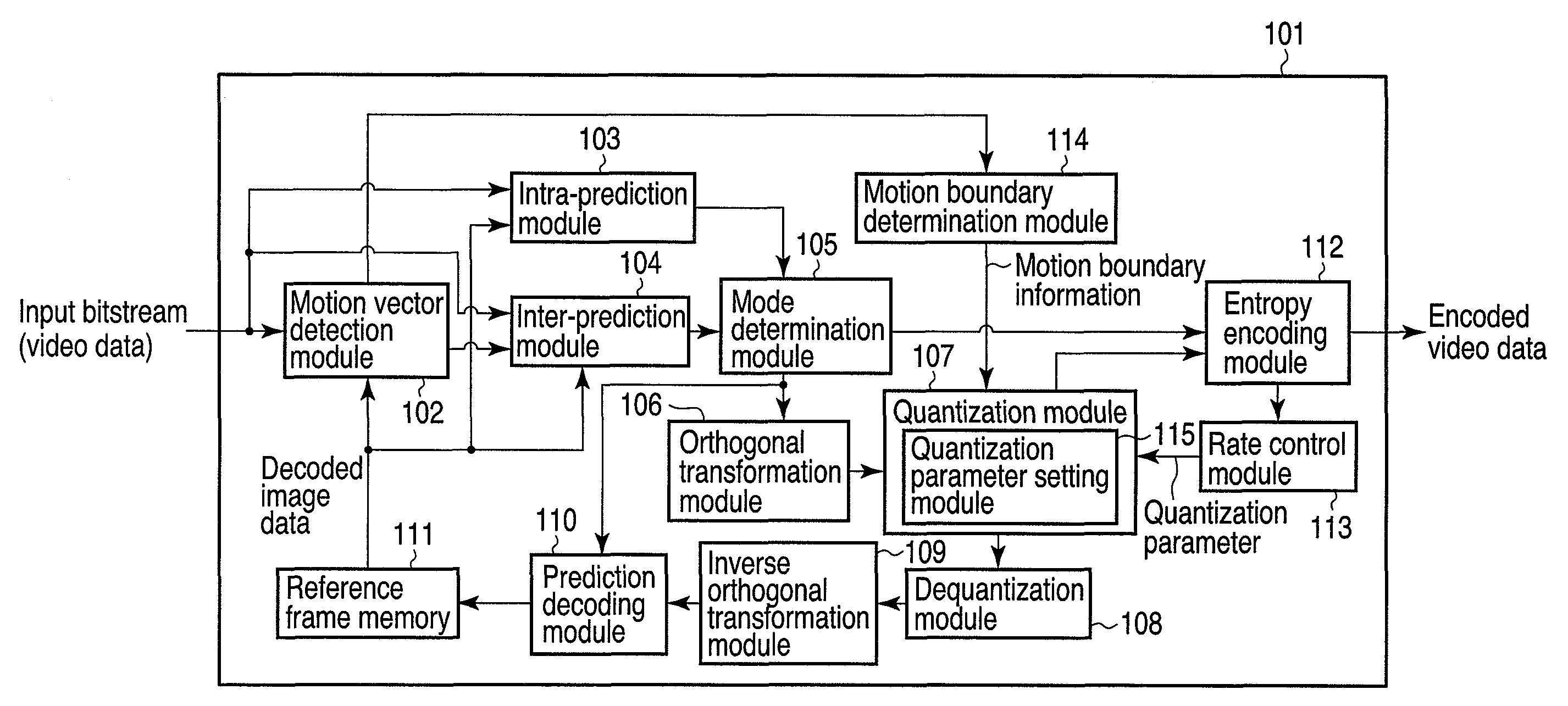
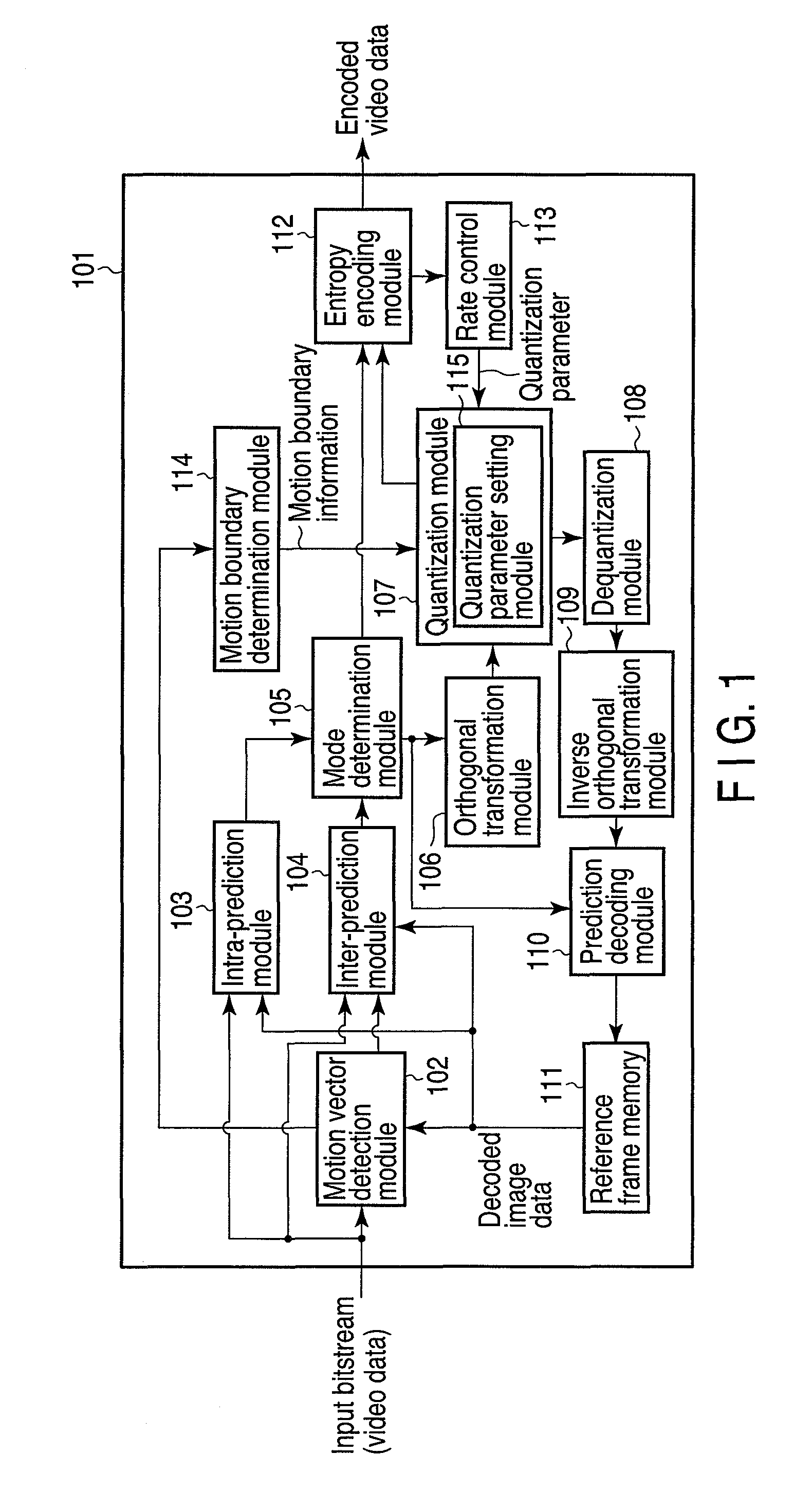
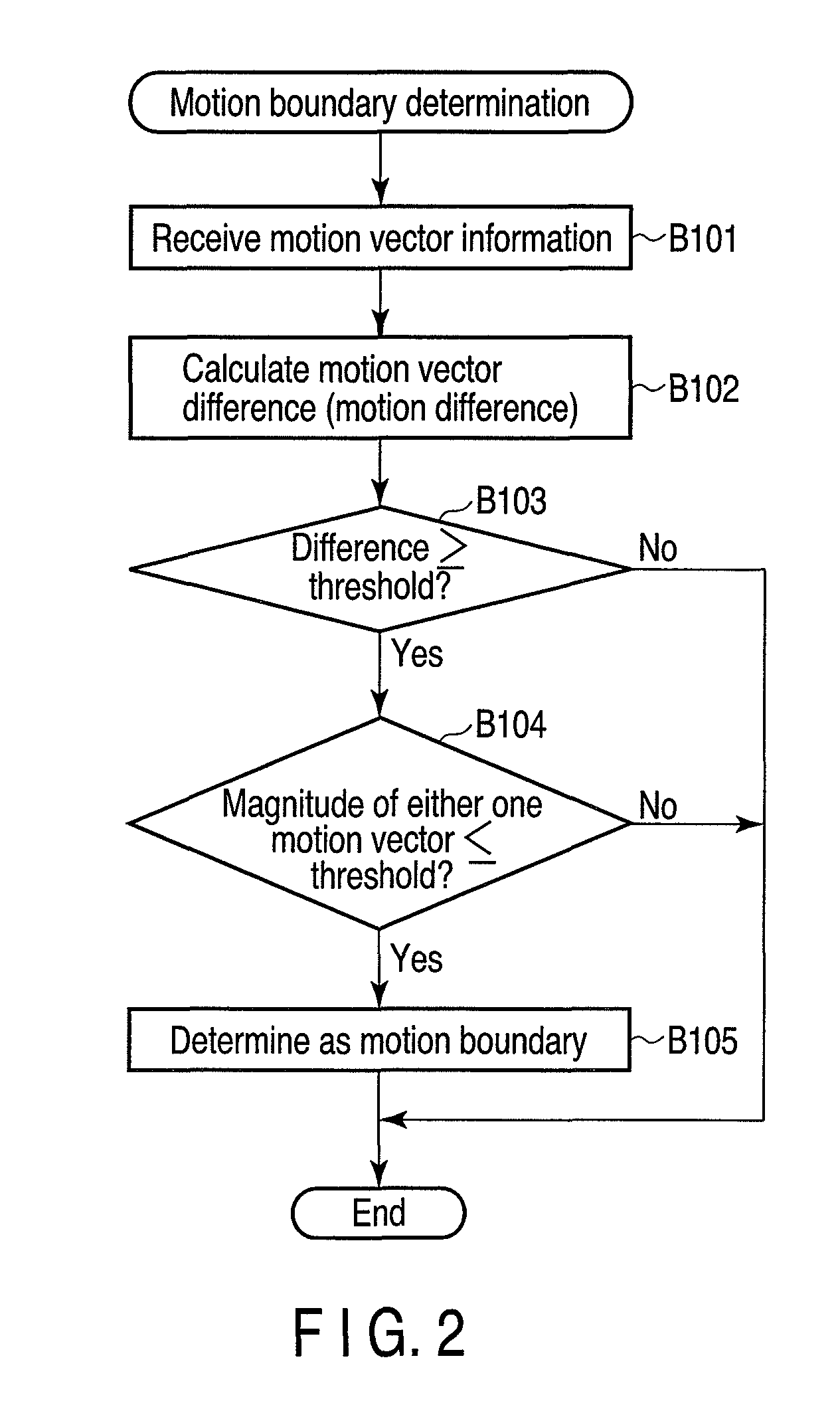
The invention relates to a video encoding apparatus and method that can efficiently compress video data to a smaller size. The apparatus uses motion-compensated prediction and discrete cosine transformation to achieve high quality video compression. The method sets quantization parameters based on the visual characteristics of the video data to eliminate degradation of image quality due to quantization. The apparatus detects motion boundaries in the video data and quantizes the blocks that border these boundaries with a smaller quantization parameter to improve the image quality. The invention can be implemented in a video encoding apparatus or an information processing apparatus. The technical effects of the invention include improved video quality and reduced data size for video transmission and storage.

Problems solved by technology

However, since there is no correlation between the activities and predictive residuals, it is difficult for the adaptive quantization method based on activities to improve the image quality of a region with a large predictive residual.

Method used


Image

  • Video encoding apparatus and video encoding method
  • Video encoding apparatus and video encoding method
  • Video encoding apparatus and video encoding method

Examples


Embodiment Construction

[0024]Various embodiments according to the invention will be described hereinafter with reference to the accompanying drawings. In general, according to one embodiment of the invention, there is provided a video encoding apparatus comprising: a motion vector calculation module configured to calculate motion vectors for respective blocks in an input image; a motion boundary detection module configured to detect a motion boundary between a motion region and a still region in the input image based on the motion vectors of the respective blocks; and a quantization parameter setting module configured to set a value of a quantization parameter used to quantize a block that borders the detected motion boundary to a value smaller than a value which is set when the block does not border the motion boundary in accordance with a detection result of the motion boundary.

[0025]A video encoding apparatus according to an embodiment of the invention is configured to input a bitstream of video data, ...


PUM


Abstract

According to one embodiment, a video encoding apparatus includes a motion vector calculation module, a motion boundary detection module, and a quantization parameter setting module. The motion vector calculation module calculates motion vectors for respective blocks in an input image. The motion boundary detection module detects a motion boundary between a motion region and a still region in the input image based on the motion vectors of the respective blocks. The quantization parameter setting module sets a value of a quantization parameter used to quantize a block that borders the detected motion boundary to a value smaller than a value which is set when the block does not border the motion boundary in accordance with a detection result of the motion boundary.

Description

CROSS-REFERENCE TO RELATED APPLICATIONS[0001]This application is based upon and claims the benefit of priority from Japanese Patent Application No. 2008-305291, filed Nov. 28, 2008, the entire contents of which are incorporated herein by reference.BACKGROUND[0002]1. Field[0003]One embodiment of the invention relates to a video encoding apparatus and video encoding method.[0004]2. Description of the Related Art[0005]A video encoding technique required to transmit and store a video signal to have a smaller data size has been put into practical use, as represented by, e.g., the MPEG2 video standard.[0006]In the MPEG2 video standard, one image is divided into blocks each of 8×8 pixels, discrete cosine transformation (DCT) as one of orthogonal transformations is applied to respective blocks, and obtained DCT coefficients are quantized to attain variable-length encoding, thus compressing the image. Using motion-compensated prediction together, the encoding efficiency can be improved using...

Claims


Application Information

Patent Timeline
Patent Type & Authority Patents(United States)
IPC IPC(8): H04B1/66H04N19/50H04N19/126H04N19/134H04N19/137H04N19/139H04N19/146H04N19/167H04N19/196H04N19/423H04N19/503H04N19/51H04N19/513H04N19/593H04N19/60H04N19/61H04N19/85H04N19/91
CPCH04N19/139H04N19/176H04N19/152H04N19/124H04N19/61
Inventor TANAKA, TAKAHIRO
Owner KK TOSHIBA
Learn More