Fall arrest assembly

Inactive Publication Date: 2011-08-23
EXPONENT CHALLENGE TECH COOP VENNOOTSCHAP MET BEPERKTE AANSPRAKELIJKHEID
View PDF25 Cites 21 Cited by
  • Summary
  • Abstract
  • Description
  • Claims
  • Application Information

AI Technical Summary

Benefits of technology

[0019]The advantage of a fall arrest assembly according to the invention is that it provides a stronger means of clamping a fall arrest system around poles or trees or other objects because the support extension is fixed rigidly to the

Problems solved by technology

As participants demand more and more excitement, the adventure course will increase in complexity and risk.
A major disadvantage of such a fall arrest a

Method used


Image

  • Fall arrest assembly
  • Fall arrest assembly
  • Fall arrest assembly

Examples


Example

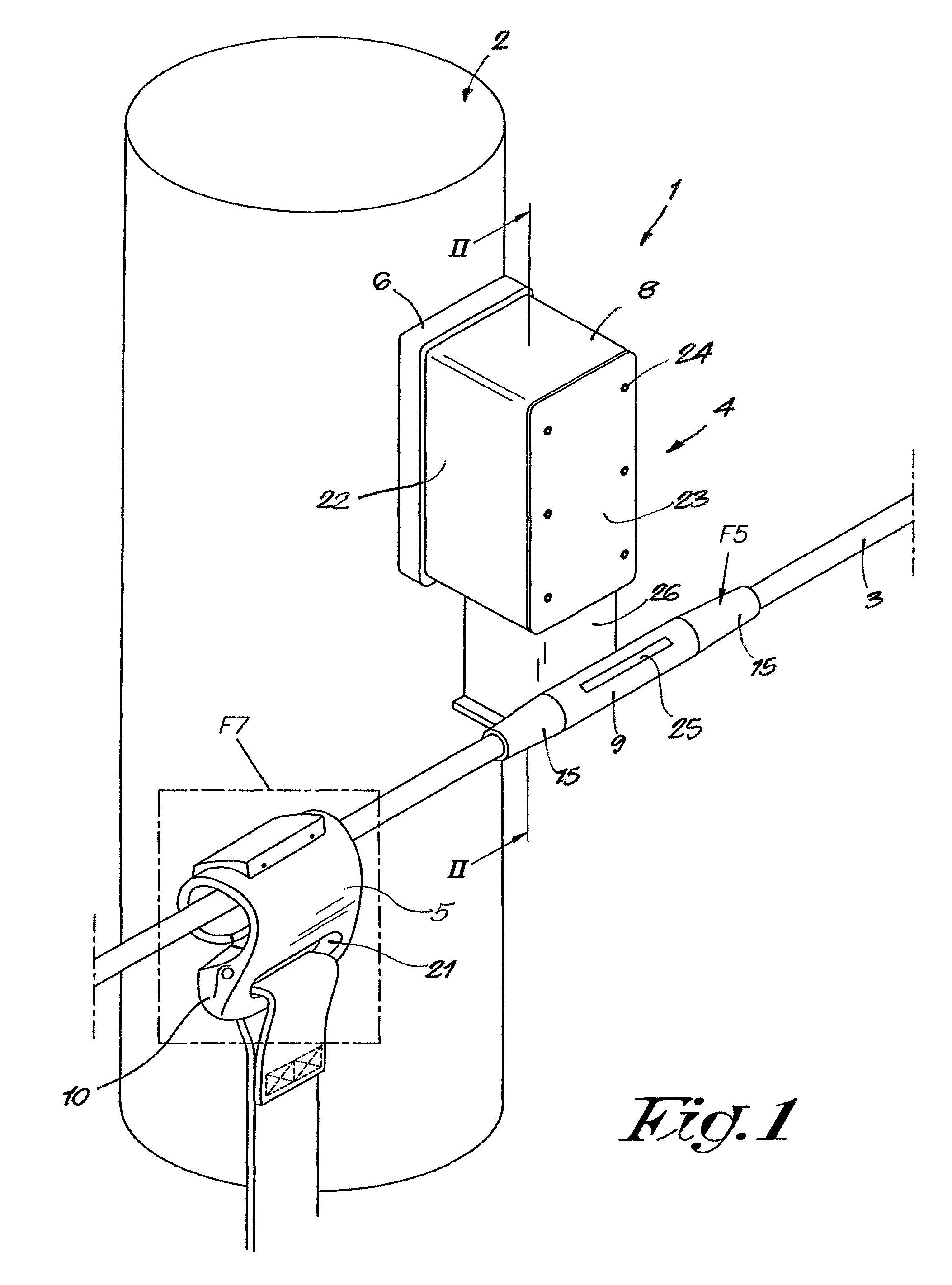
[0055]FIG. 1 shows the schematics to attach a fall arrest assembly 1 around one of a plurality of objects 2 whereby the fall arrest assembly 1 has a belay line 3 extending between anchor stations 4 that are adapted to slidably receive a shuttle 5 coupled to a person traversing the belay lines 3.

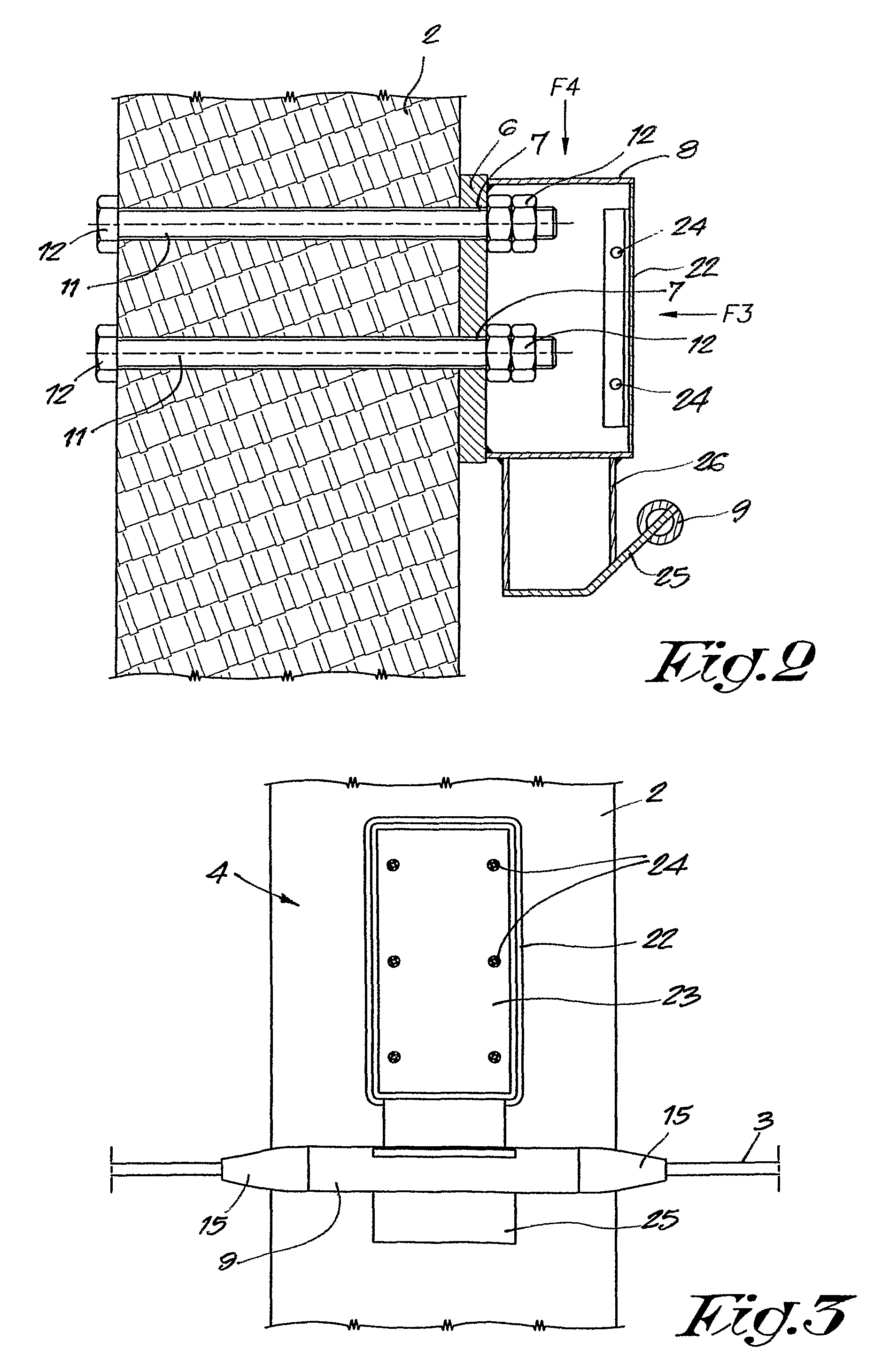
[0056]FIG. 2 shows that the anchor station 4 comprises a mounting plate 6 defining a plurality of openings 7 therethrough.

[0057]The anchor station 4 of the assembly 1 further comprises a support extension 8 which is fixed rigidly to the mounting plate 6 and carries a shuttle guide 9 thereon. The shuttle guide 9 is configured for slidable passage of a shuttle 10 thereover and is further configured to be coupled to the belay lines 3.

[0058]As shown in FIGS. 2 and 3, each anchor station 4 of the fall arrest assembly 1 further comprises a plurality of anchor elements 11 having a section configured to extend through the plurality of openings 7 in the mounting plate 6.

[0059]FIG. 2 also shows that th...


PUM


Abstract

A fall arrest assembly having belay lines and anchor stations extending between support structures and which slidably receive a shuttle mounted to a person traversing the belay lines, the assembly including a mounting plate having a plurality of openings therethrough and a supporting extension fixed rigidly thereto and wherein the support extension carries a shuttle guide coupled to the belay lines and configured for slidable passage of a shuttle there over, and a plurality of anchor elements having a section configured to extend through the plurality of openings in the mounting plate and clamps for securing the anchor elements to the support structures.

Description

BACKGROUND OF THE INVENTION[0001]1. Field of the Invention[0002]The present invention relates to a fall arrest assembly.[0003]2. Brief Description of the Related Art[0004]In a typical fall arrest assembly or personal belay system, the user is fitted with a harness that may be removably clipped to a shuttle or glider. The shuttle is configured to slide easily along an array of belay lines in the form of suspended ropes or cables. Common forms of personal fall arrest assemblies are used in the construction and building maintenance industries where workers are performing tasks at dangerous heights, such as high-rise building construction, window washing and roof repairs. In these common systems, the runs are relatively short and often include a cable run dedicated to each worker. Moreover, the cable runs are usually fixed, stable and geometrically simple and predictable. For instance, in building constructions, the runs follow existing horizontal beams of the building and are anchored ...

Claims


Application Information

Patent Timeline
IPC IPC(8): B61B7/00
CPCA62B35/0087A62B35/0056
Inventor MAES, KOENMAES, BART
Owner EXPONENT CHALLENGE TECH COOP VENNOOTSCHAP MET BEPERKTE AANSPRAKELIJKHEID
Why Eureka
Try Eureka