Drive unit for hybrid vehicle

a hybrid vehicle and drive unit technology, applied in the direction of gas pressure propulsion mounting, electric energy management, electric devices, etc., can solve the problems of limited mounting space for the drive unit on the motorcycle, increased environmental awareness of the vehicle manufacturer and the consuming public, and further limited mounting space, etc., to achieve the effect of convenient mounting and relative compactness

Inactive Publication Date: 2011-08-23
YAMAHA MOTOR CO LTD
View PDF135 Cites 8 Cited by
  • Summary
  • Abstract
  • Description
  • Claims
  • Application Information

AI Technical Summary

Benefits of technology

[0013]The generator, the motor and the power distributing device, in one example, are not juxtaposed with the crankshaft, because the generator, the motor and the power distributing device are disposed on the single different shaft which is different from the crankshaft of the engine and extends parallel to the crankshaft. That is, the structure including the engine, the generator, the motor, and the power distributing device is not elongated and, thus, can be relatively compact. Thus, with the crankshaft extending in the transverse direction, the generator, the engine and the motor can be mounted without protruding in the transverse direction. The drive unit thus can be suitably and easily mounted on a vehicle, e.g., a motorcycle, which only has such a limited space.

Problems solved by technology

Recently, vehicle manufacturers and the consuming public have become more sensitive to environmental issues.
However, space for mounting the drive unit on a motorcycle is limited to a portion of the vehicle body located between a front wheel and a rear wheel and below a seat.
The mounting space thus can be further limited.
Accordingly, it is extremely difficult to provide the motorcycle with the drive unit that has the arrangement in which the engine, the generator, the power distributing mechanism and the motor are arranged coaxially and in series.
As a result, no motorcycle has been developed in which the drive unit constructed as discussed above is efficiently mounted.

Method used


Image

  • Drive unit for hybrid vehicle
  • Drive unit for hybrid vehicle
  • Drive unit for hybrid vehicle

Examples


Embodiment Construction

[0022]As used herein, a “drive unit” refers to an assembled unit, which may have a plurality of components, all of which may or may not be held in a common housing. Additionally, as used in the embodiments herein, the terms “front,”“forward,”“rear,”“rearward,”“left,”“right,”“top,”“upper,”“bottom” and “lower” are defined from the perspective of user riding the hybrid vehicle.

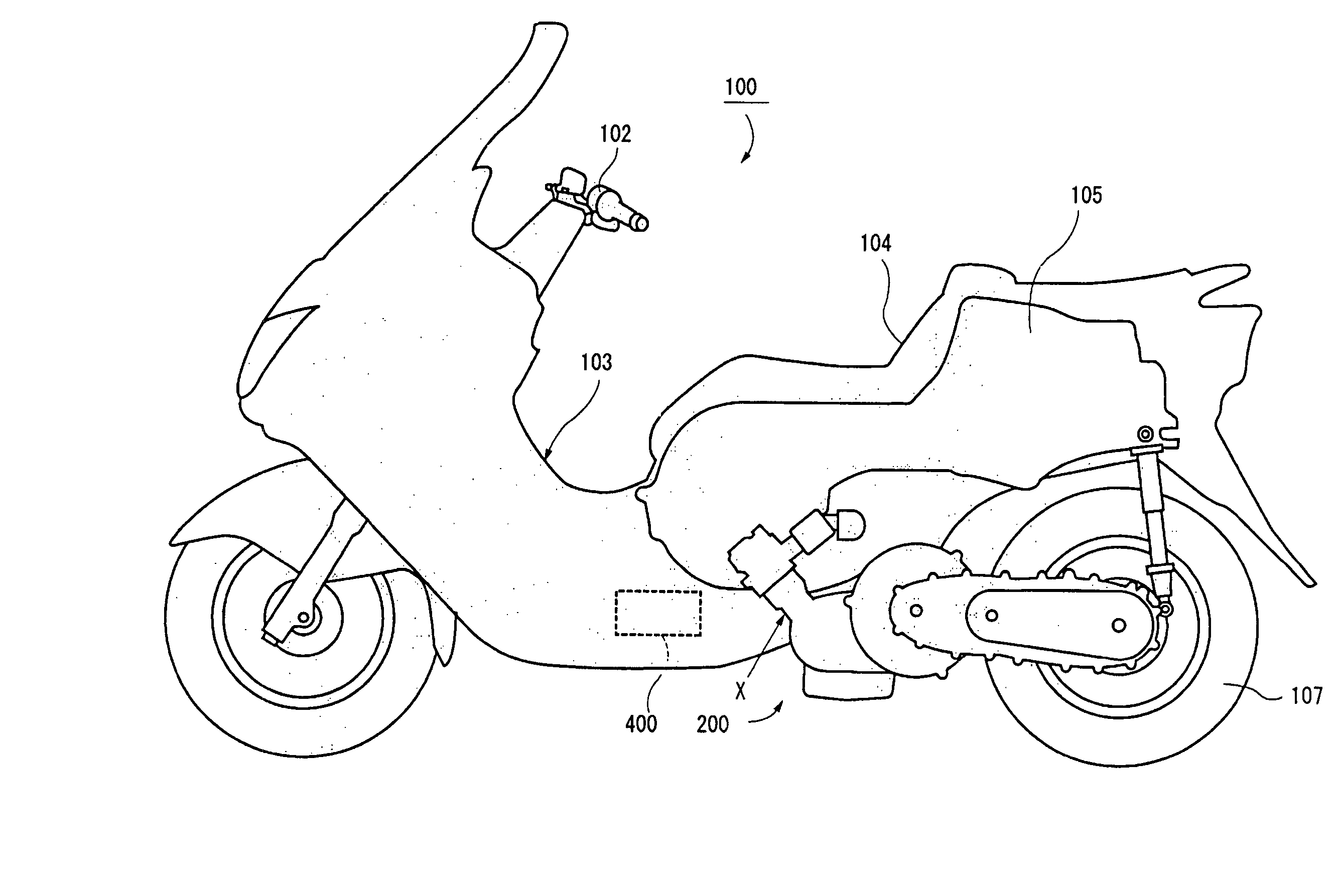
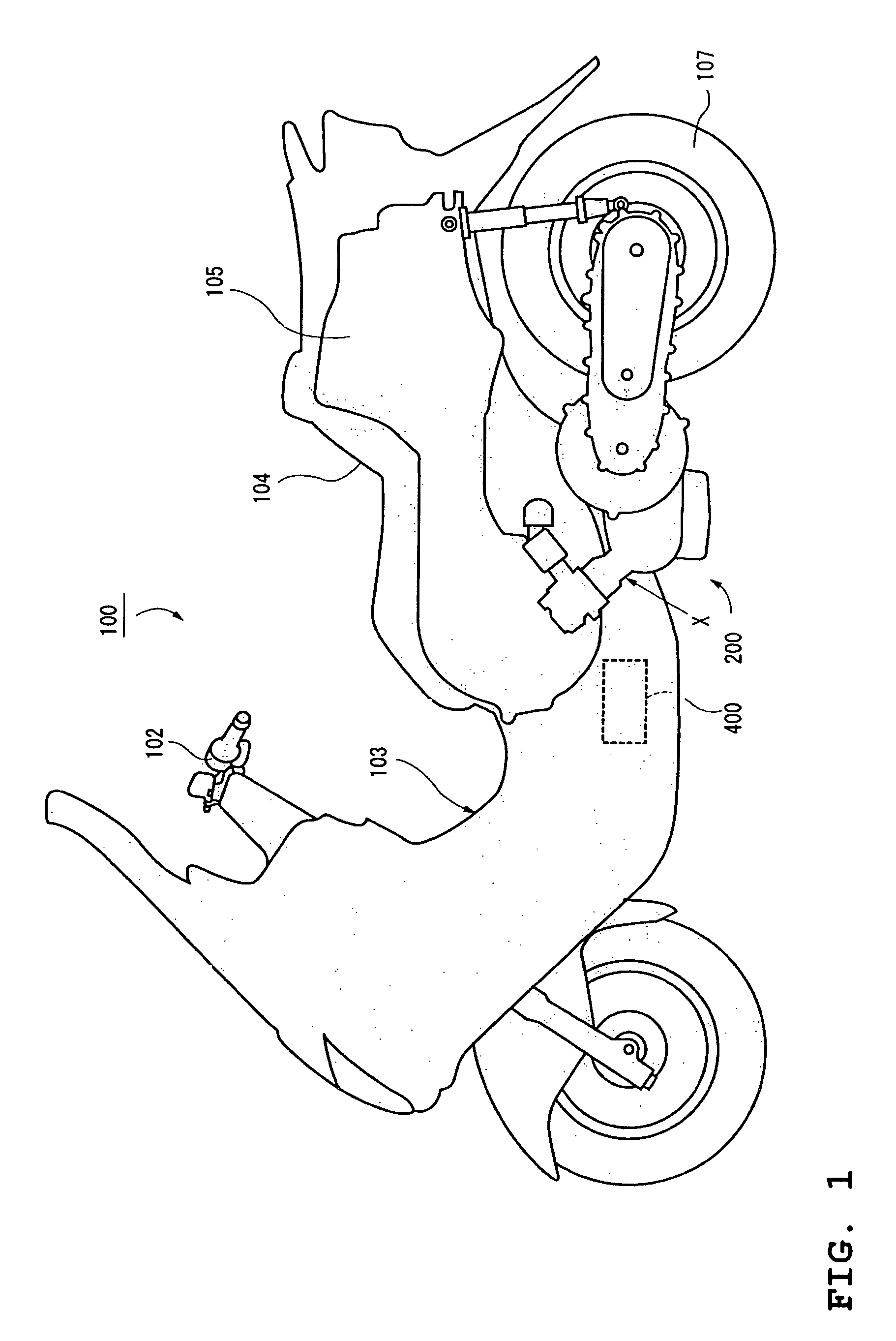
[0023]FIG. 1 is a left side elevational view of a scooter type hybrid motorcycle, which is an example of a hybrid vehicle on which the drive unit for a hybrid vehicle according to an embodiment of this invention is mounted.

[0024]The scooter type motorcycle of FIG. 1 incorporates a series / parallel hybrid mechanism in which either one of an engine and an electric motor, both of which are power sources, individually drives a wheel, or both of the engine and the motor are combined to drive the wheel. More specifically, in the hybrid vehicle (called “scooter type motorcycle” below), a power dividing mechanism divides ...


PUM


Abstract

A drive unit includes an engine, a generator, an electric motor and a power distributing device. The engine drives the generator to generate electric power. The electric motor is driven by the electric power generated by the generator and rotates a drive wheel. The power distributing device distributes the drive power generated by the engine between the generator and the drive wheel. A crankshaft of the engine can extend in a transverse direction of the vehicle. The generator, the motor and the power distributing device are disposed on a shaft, which is different from the crankshaft and extends substantially parallel to the crankshaft. The power of the engine and the drive force of the motor are output from a portion of the shaft through the power distributing device and the rotor of the motor.

Description

CROSS-REFERENCE TO RELATED APPLICATIONS[0001]The present application is based on and claims priority under 35 U.S.C. §119 to Japanese Patent Application No. 2005-076035, filed on Mar. 16, 2005, the entire contents of which is expressly incorporated by reference herein.BACKGROUND OF THE INVENTION[0002]1. Field of the Invention[0003]This invention relates to a hybrid type drive unit including an engine and an electric motor both mounted on a vehicle (e.g., a hybrid type motorcycle) and selectively used for driving one or more drive wheels.[0004]2. Description of the Related Art[0005]Conventionally, vehicles such as motorcycles and automobiles typically have an engine for driving one or more wheels thereof. Recently, vehicle manufacturers and the consuming public have become more sensitive to environmental issues. It is thus desired to reduce carbon dioxide discharged from vehicles powered by an internal combustion engine or to reduce substances which give rise to the pollution of the ...

Claims


Application Information

Patent Timeline
Patent Type & Authority Patents(United States)
IPC IPC(8): B60L5/00B60K6/24B60K6/365B60K6/40B60K6/445B60K17/04B60L50/16B62K11/00B62M7/06B62M23/02F16H48/10F16H55/18
CPCB60K6/26B60K6/40B60K6/445B62M7/12B60L11/14B60L15/2009B60K6/24B60G2204/30Y10S903/952B60Y2200/126B62K2202/00F16H2037/0866Y02T10/6239Y02T10/6295Y02T10/7275Y02T10/70Y02T10/7077Y02T10/648B60L2200/12B60L2220/42B60L2240/12B60L2240/421Y10S903/951Y10S903/916Y02T10/72B60L50/16Y02T10/62Y02T10/64Y02T10/7072
Inventor SAITOU, TETSUSHI
Owner YAMAHA MOTOR CO LTD
Why Eureka
Try Eureka