Steam-water separator

a technology of steam-water separator and separator, which is applied in the direction of steam separation arrangement, separation process, greenhouse gas reduction, etc., can solve the problems of reducing steam-water separating efficiency, achieve enhanced steam-water separating efficiency, prevent steam from flowing, and enhance steam-water separating efficiency

Active Publication Date: 2011-08-23
MITSUBISHI HEAVY IND LTD
View PDF31 Cites 6 Cited by
  • Summary
  • Abstract
  • Description
  • Claims
  • Application Information

AI Technical Summary

Benefits of technology

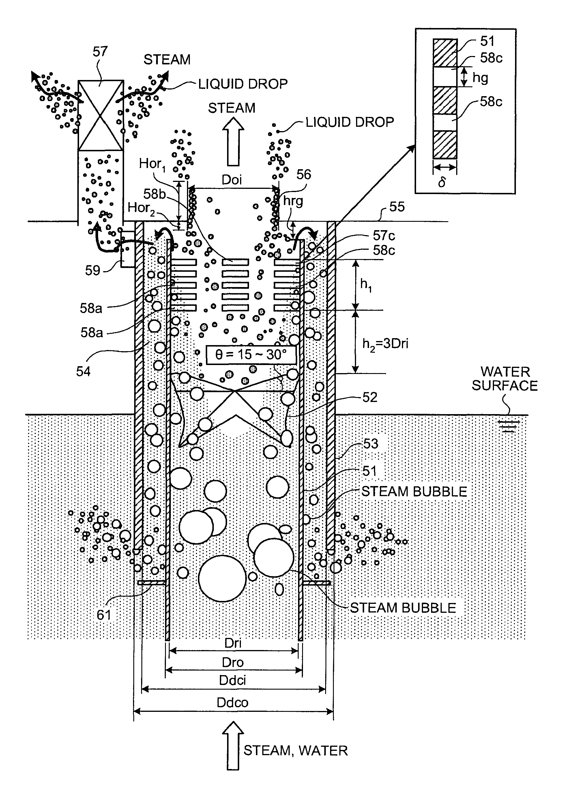
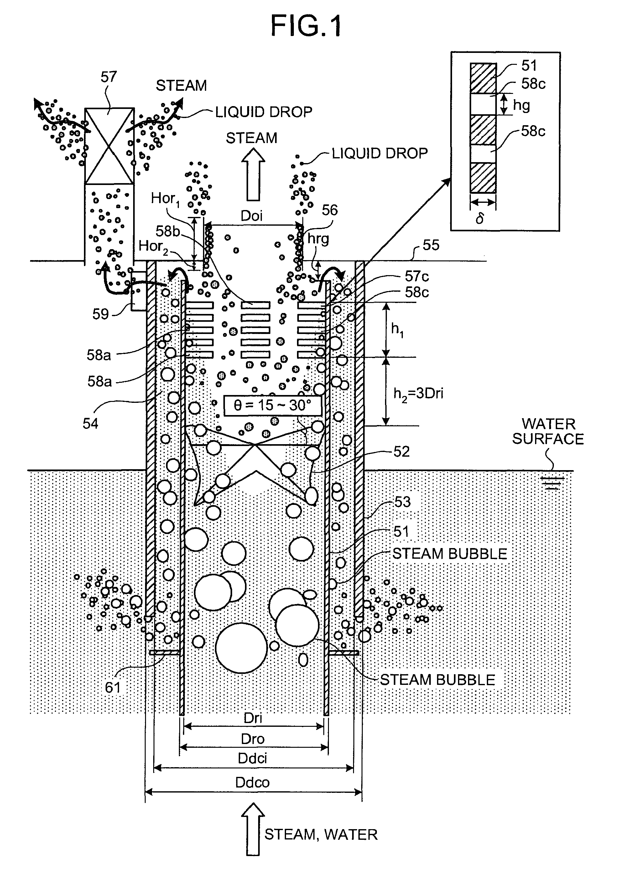
[0024]According to the steam-water separator of the present invention, the steam-water riser pipe that has a plurality of the openings on its wall surface at the upper end and through which a two-phase flow of the water and the steam goes up is provided, the swirl vane is provided inside the steam-water riser pipe, the downcomer barrel is provided surrounding the steam-water riser pipe to form the annular downcomer space, the deck plate that is arranged opposite the upper ends of the steam-water riser pipe and the downcomer barrel with the predetermined space therefrom and that includes the orifice arranged above the steam-water pipe is provided, and the aperture ratios of the plural openings formed on the steam-water riser pipe are set at from 30% to 70%. Therefore, the two-phase flow of the water and the steam that is introduced into the steam-water riser pipe from its lower end goes upward and then is lifted while being swirled by the swirl vane, and the water deposits on the inner face of the steam-water riser pipe and is lifted while becoming a liquid film flow. At this moment, because the aperture ratios of the plural openings formed on the wall surface of the steam-water riser pipe at the upper end are set at from 30% to 70%, the water appropriately flows into the downcomer space of the downcomer barrel and falls down without being carried over from the orifice or carried under to outside the downcomer barrel. On the other hand, the steam flows upward while being swirled at the upper part of the steam-water riser pipe, and is appropriately discharged above the deck plate through the orifice without absorbing the water. As a result, the steam-water separating efficiency is enhanced.
[0025]According to the steam-water separator of the present invention, the openings formed on the steam-water riser pipe are plural horizontal slits arranged in parallel along the vertical direction, and the heights of the slits are set at from half to twice the thickness of the steam-water riser pipe. Therefore, it is possible to prevent the steam from flowing into the slits, and cause only the water to appropriately flow into the downcomer space through these slits.
[0026]According to the steam-water separator of the present invention, the distance between the openings formed on the steam-water riser pipe and the swirl vane is set at from 1 time to 2.5 times the internal diameter of the steam-water riser pipe. Therefore, the two-phase flow of the water and the steam is lifted while being swirled by the swirl vane so that, after being separated into the water and the steam, the water appropriately flows into the downcomer space while the steam is appropriately discharged through the orifice, which enhances the steam-water separating efficiency.
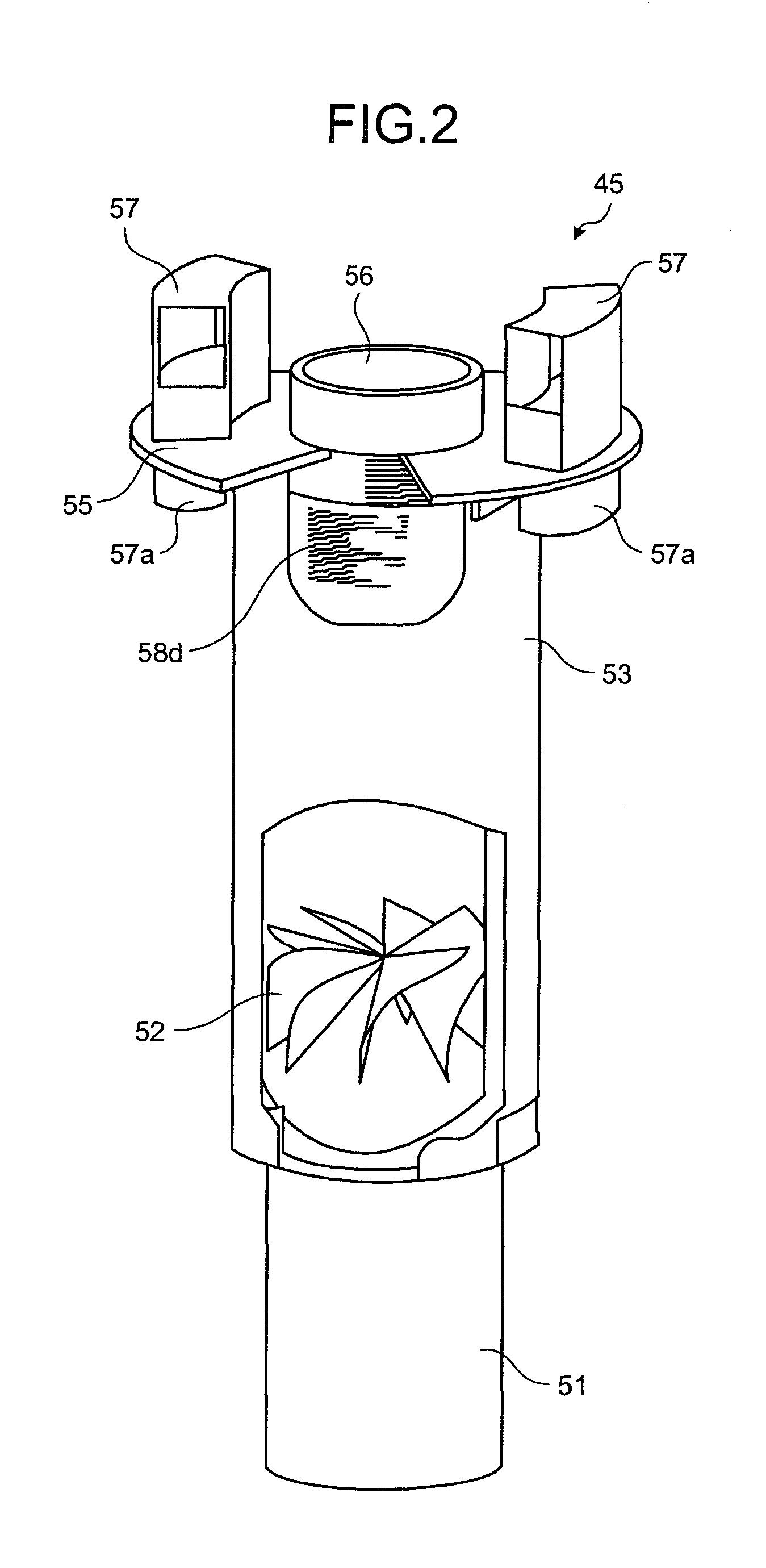
[0027]According to the steam-water separator of the present invention, the two guide units that discharge swirling flows of the steam are provided on the wall surface at the upper end of the downcomer barrel, equally spaced in the circumferential direction, and four openings are provided on the steam-water riser pipe, equally spaced in the circumferential direction of the steam-water riser pipe, and two of the four openings are located opposite the guide units. Therefore, the water separated by being lifted and swirled by the swirl vane passes through the slits, and flows to outside the downcomer barrel through the guide units together with the steam. Accordingly, the water and the steam can be processed with appropriately separated each other.
[0028]According to the steam-water separator of the present invention, the vents are provided on the deck plate downstream of the swirling flows of the steam discharged from the guide units. Therefore, the steam discharged outward from the downcomer barrel through the guide units can be appropriately discharged through the vents above the deck plate.
[0029]According to the steam-water separator of the present invention, the twist angle of the swirl vane is set at from 15 degrees to 30 degrees. Therefore, by applying an appropriate whirling power to the two-phase flow by ways of the swirl vane, the water and the steam can be reliably separated.

Problems solved by technology

However, some of the water escapes out of the downcomer barrel from the top thereof, and comes to flow out of the vent above the deck plate, being accompanied by the steam moving upwards outside the downcomer barrel, which decreases steam-water separating efficiency.

Method used


Image

  • Steam-water separator
  • Steam-water separator
  • Steam-water separator

Examples


embodiments

[0067]FIG. 1 is a schematic diagram of relevant parts of a steam-water separator according to an embodiment of the present invention; FIG. 2 is a partly-broken perspective view of the steam-water separator of the embodiment; FIG. 3 is a plan view of the steam-water separator of the embodiment; FIG. 4 is a schematic diagram of slits formed on a riser; FIG. 5 is a schematic diagram of guide units provided on the riser; FIG. 6 is a plan view of the guide unit; FIG. 7 is a cross section of an upper part of the steam-water separator of the embodiment; FIGS. 8A and 8B are schematic diagrams of a swirl vane; FIG. 9 is a graph of a carryunder flow rate with respect to a slit aperture ratio; FIG. 10 is a graph of wetness fraction and a carryunder flow rate with respect to a ratio between height and thickness of the slits; FIG. 11 is a graph of wetness fraction with respect to a distance between the slits and the swirl vane; FIG. 12 is a graph of wetness fraction and resistance with respect t...


PUM

PropertyMeasurementUnit
twist angleaaaaaaaaaa

Abstract

In a steam-water separator, a swirl vane (52) is provided inside a riser (51), an annular downcomer space (54) is formed by providing a downcomer barrel (53) outside the riser (51), a deck plate (55) is arranged above the riser (51) and the downcomer barrel (53) with a predetermined space therefrom, an orifice (56) and vents (57) are formed, and aperture ratios of plural slits (58a, 58b, 58c, and 58d) formed on the riser (51) are set at from 30% to 70%. Accordingly, the steam and the water is appropriately separated, and the separated steam is reliably discharged upward from the orifice while the separated water is allowed to reliably flow down through the downcomer space, thereby enhancing steam-water separating efficiency.

Description

TECHNICAL FIELD[0001]The present invention relates to a steam-water separator that separates a two-phase flow of steam and liquid into the steam and the liquid.BACKGROUND ART[0002]For example, a pressurized water reactor (PWR: Pressurized Water Reactor), using light water as a reactor coolant and a neutron moderator, runs it as non-boiling, high-temperature and high-pressure water throughout a reactor core, sends the high-temperature and high-pressure water to a steam generator for generation of steam by heat exchange, and sends the steam to a turbine generator for generation of electricity. The pressurized water reactor transfers the heat of high-temperature and high-pressure primary cooling water to secondary cooling water by way of the steam generator, generating the steam from the secondary cooling water. In the steam generator, the primary cooling water flows inside a large number of narrow heat-transfer tubes, and the heat of the primary cooling water is transferred to the sec...

Claims


Application Information

Patent Timeline
Patent Type & Authority Patents(United States)
IPC IPC(8): B04C3/00
CPCF22B37/327Y02E30/00Y10T137/3003B01D45/12F22B37/32G21D1/00
Inventor KONDO, YOSHIYUKISUZUTA, TADAHIKOMIZUTANI, TOSHIYUKIHIRAO, YASUHIKO
Owner MITSUBISHI HEAVY IND LTD
Why Eureka
Try Eureka