Appliance with a vacuum-based reverse airflow cooling system

a reverse airflow cooling and vacuum technology, applied in the field of applications, can solve the problems of limit the location of the oven control panel, damage and malfunction,

Active Publication Date: 2011-08-30
HAIER US APPLIANCE SOLUTIONS INC
View PDF54 Cites 22 Cited by
  • Summary
  • Abstract
  • Description
  • Claims
  • Application Information

AI Technical Summary

Problems solved by technology

This design, however, limits where the oven control panel can be located, constraining it usually to a dedicated, separate area over the oven door where an air intake is sometimes located.
But oven doors in dual-cavity ovens employing these typical cooling configurations prove to be too hot to serve as a suitable site for the control panel, which can be damaged and malfunction because of the excessive heat.

Method used


Image

  • Appliance with a vacuum-based reverse airflow cooling system
  • Appliance with a vacuum-based reverse airflow cooling system
  • Appliance with a vacuum-based reverse airflow cooling system

Examples


Embodiment Construction

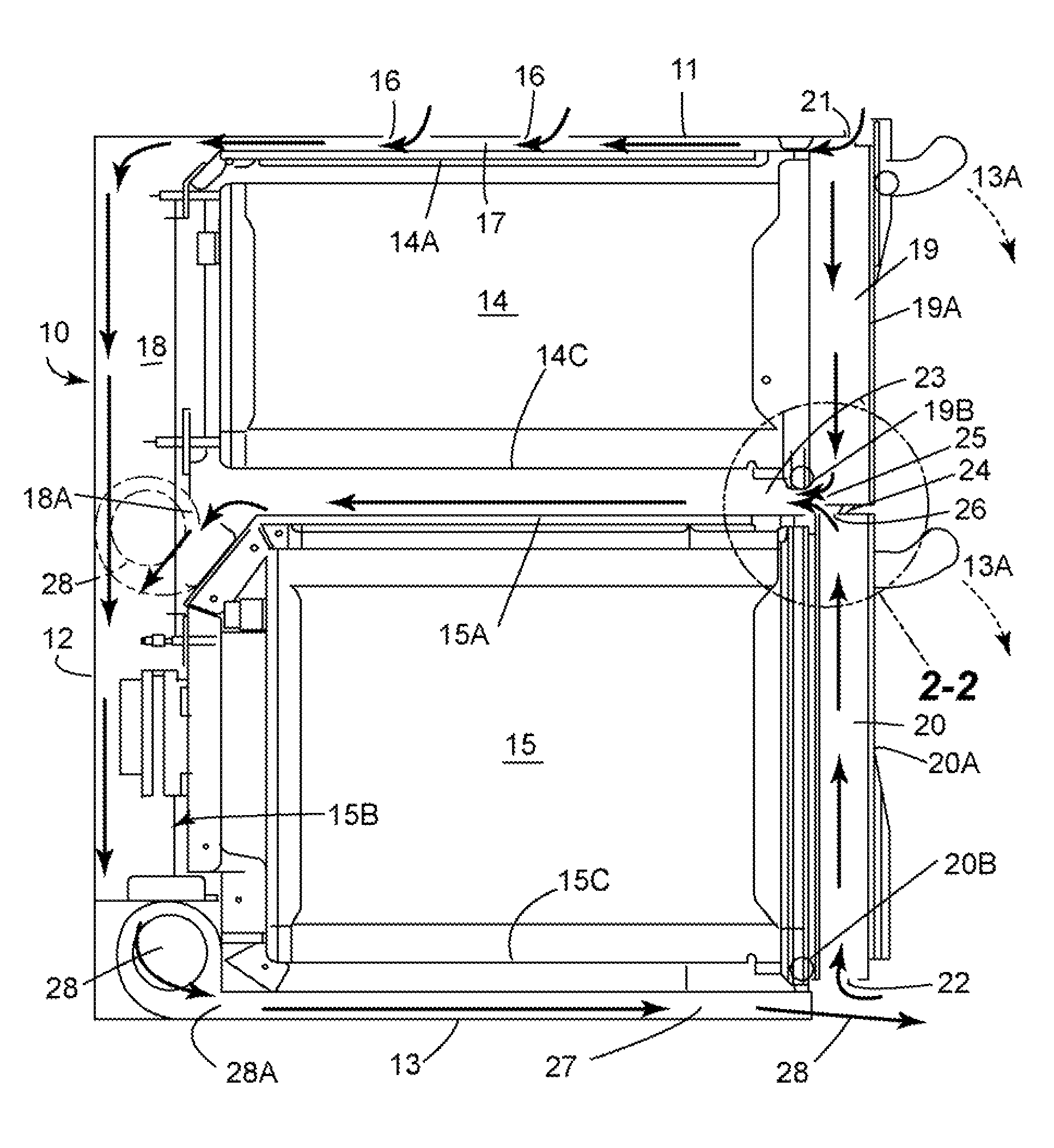
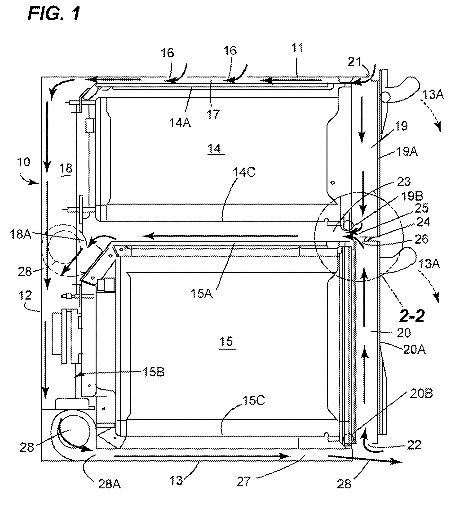
[0021]An exemplary appliance such as a dual-cavity oven incorporating an embodiment of the reverse airflow cooling system of the present invention is generally designated by reference numeral 10 in FIG. 1. FIG. 1 is a schematic, elevational side view of a cross section of such an oven, showing an oven cabinet or a main body comprising a top 11, a back 12, opposing sides 33 (see FIG. 5), a bottom 13 and an open front at side 13A. The top 11 is shown having air inlets 16. These can be vents, grill, holes or other configurations as known in the art, spaced across top 11. The number and pattern of the air inlets may vary depending on the inlet airflow requirements for a particular appliance configuration.

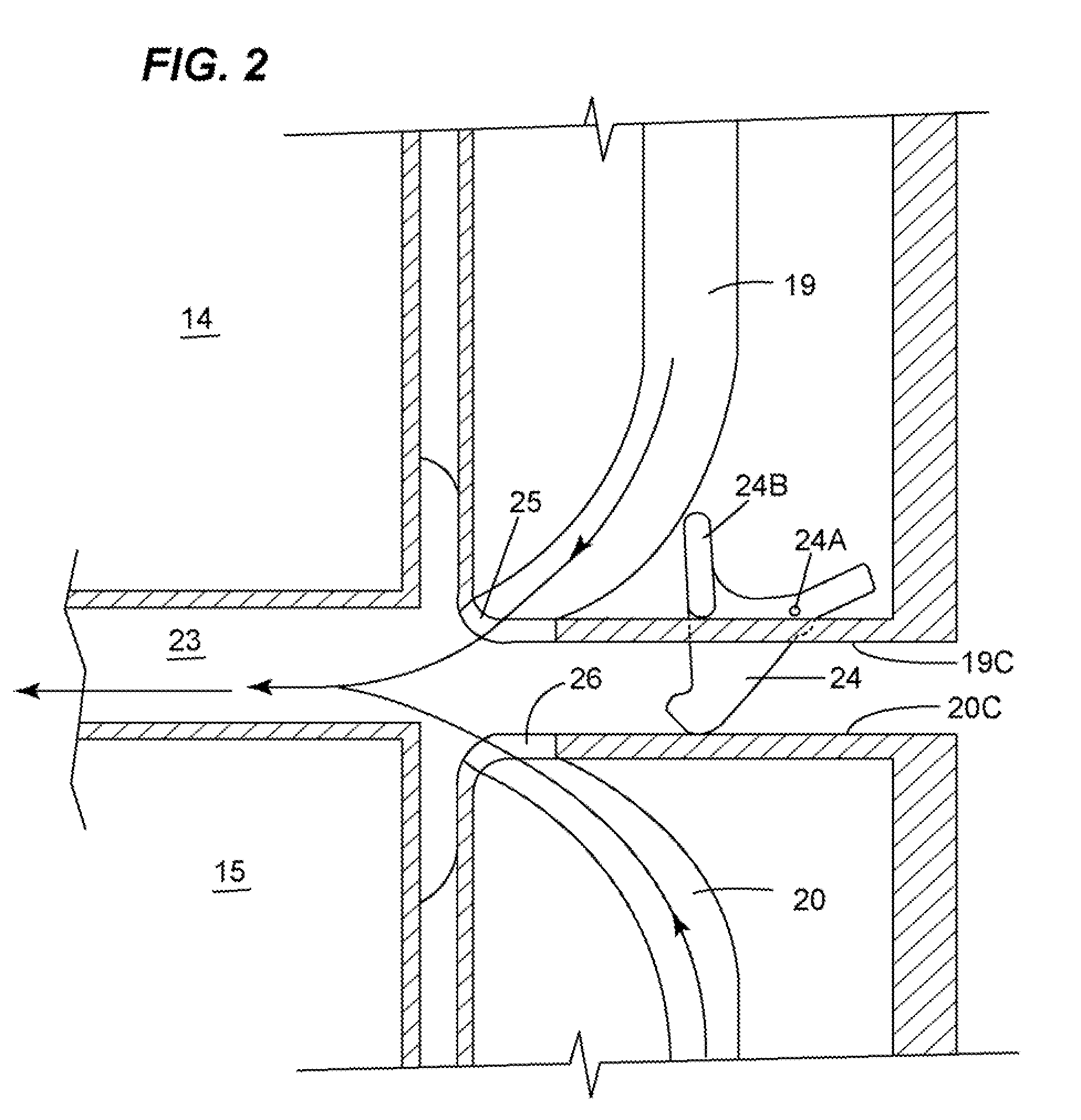
[0022]The oven cabinet surrounds or defines an upper oven cavity or chamber 14 and a lower oven cavity or chamber 15. As exemplified in FIG. 1, the top 11 of the oven cabinet and the back 12 of the oven cabinet are outwardly spaced from the upper and lower oven cavities 14 and 15. The s...


PUM


Abstract

An appliance is disclosed. The appliance includes a main body defining a cavity and an air channel which is in flow communication with an outside of the appliance; an access door supported by the main body for selectively closing the cavity, the access door having an airway in flow communication with the outside of the appliance and the air channel; a fan disposed in the air channel; and an Human Machine Interface disposed on or in the access door. When activated, the fan causes ambient air from the outside of the appliance to pass through the airway before entering the air channel so that the access door is cooled off by the ambient air.

Description

CROSS-REFERENCE TO RELATED APPLICATIONS[0001]This application relates to the commonly owned application entitled “Appliance with a Vacuum-Based Reverse Airflow Cooling System Using One Fan”, Ser. No. 12 / 209,545, filed concurrently.BACKGROUND OF THE INVENTION[0002]The present invention relates generally to an appliance. More particularly, the present invention relates to an appliance with a vacuum-based reverse airflow cooling system.[0003]Dual-cavity ovens typically draw in ambient or cooling air via intakes located above the upper oven cavity and at the top of the oven where the controls are situated. The air then encounters a fan, which in turn blows the air down the back of the upper and lower oven units. The exhaust for this type of system is usually evacuated at locations between the upper and lower oven units and also below the lower oven unit on the front side of the oven.[0004]This design, however, limits where the oven control panel can be located, constraining it usually t...

Claims


Application Information

Patent Timeline
Patent Type & Authority Patents(United States)
IPC IPC(8): F24C15/32
CPCF24C15/006F24C7/085F24C15/02
Inventor WATKINS, DEREK LEEARMSTRONG, JAMESBARBER, PHILIP AMESBRONIAK, JAY ANDREWFROELICHER, STEVE B.LAUNDROCHE, KEVIN SCOTTMCGONAGLE, MICHAEL PAUL
Owner HAIER US APPLIANCE SOLUTIONS INC
Why Eureka
Try Eureka