
Monitor for measuring improvement in involuntary breathing

a monitoring device and involuntary breathing technology, applied in the field of medical monitors, can solve the problems of limiting the effectiveness and reliability of a spirometer, affecting reducing the safety of patients, so as to avoid unnecessary overdose and ineffective medications, and measure and monitor involuntary breathing.

Active Publication Date: 2011-08-30
CAO GROUP
View PDF2 Cites 4 Cited by
  • Summary
  • Abstract
  • Description
  • Claims
  • Application Information

AI Technical Summary

Benefits of technology

[0006]The present device provides a means to measure and monitor the involuntary breathing of a patient with lung impairment. The device monitors involuntary breathing and records the data in real time. The device fits into a treatment mask or tube, thus continuous monitoring and treatments can take place without removing the mask or tube. The breathing improvement monitor will allow a health care professional to monitor the breathing of a patient while medications are administered. The device will direct the health care professional to determine if a given medication or treatment is effective and whether multiple treatments are necessary, thus avoiding an unnecessary overdose and any ineffective medications.

Problems solved by technology

Current types of supplemental masks and tubes have no means to monitor whether any given medication has improved the breathing conditions of a patient.
These two factors, understanding and exact execution, limit the effectiveness and reliability of a spirometer as consecutive measurements with a spirometer do not give consistent results.
Young children are really at a disadvantage because they must be able to understand what is required to perform the measurement and then command their bodies to execute those requirements in the exact same manner as previous tests.
The measurement of voluntary breathing is unpredictable, especially in children.
As such, measurement of involuntary breathing avoids the understanding and execution of breathing tests, which are the main cause of unreliability.

Method used


Image

  • Monitor for measuring improvement in involuntary breathing
  • Monitor for measuring improvement in involuntary breathing
  • Monitor for measuring improvement in involuntary breathing

Examples


Embodiment Construction

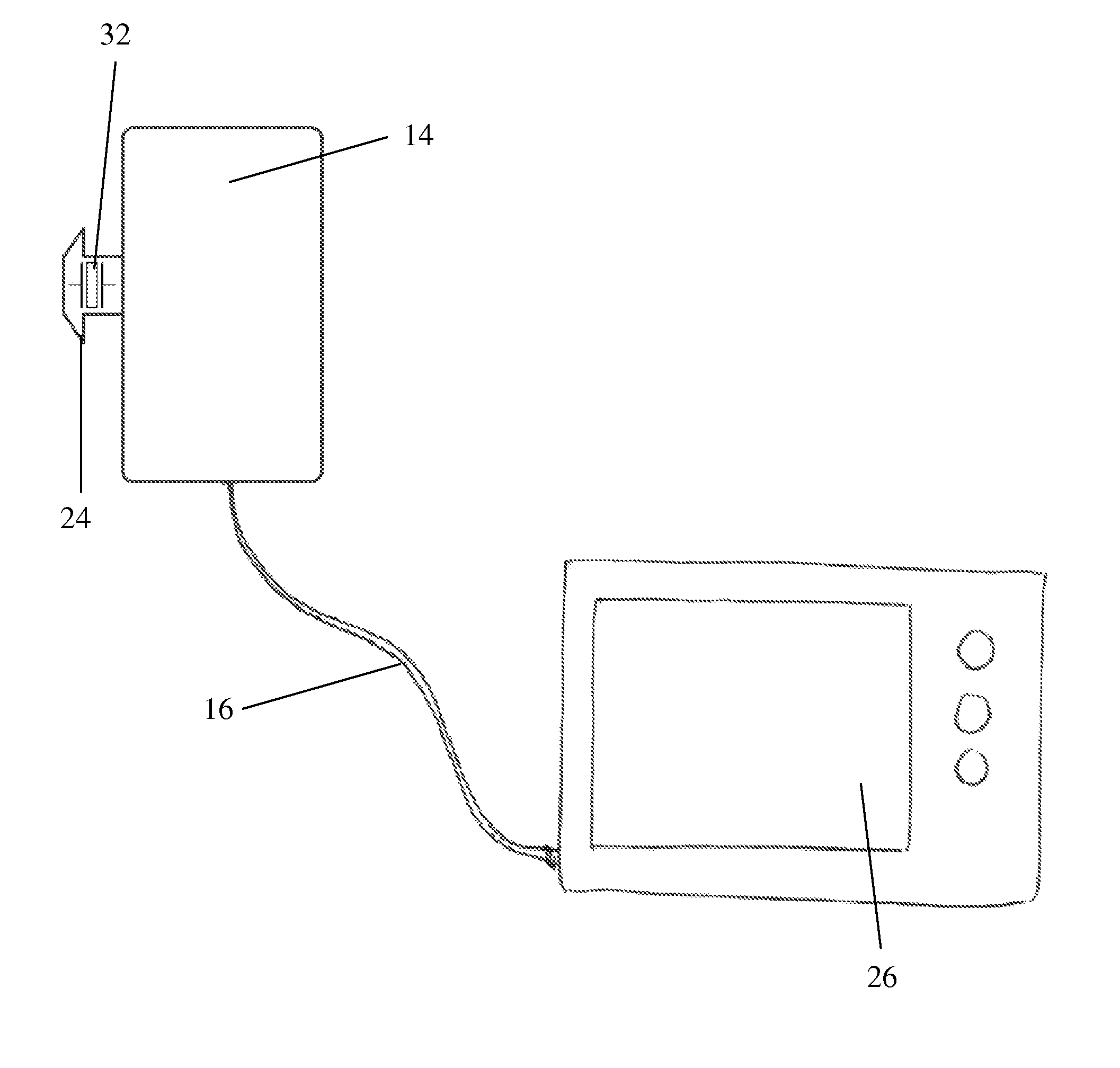
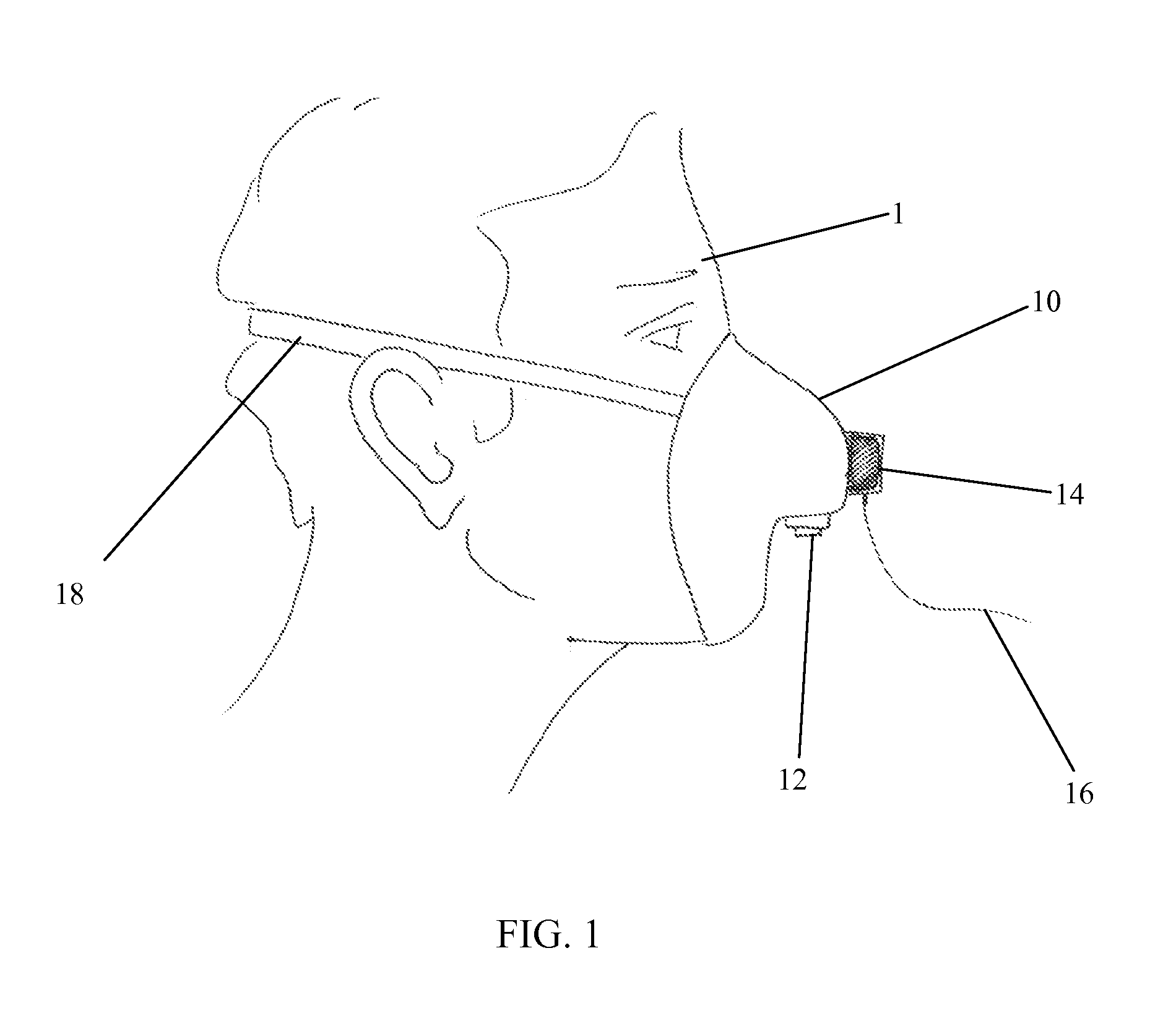
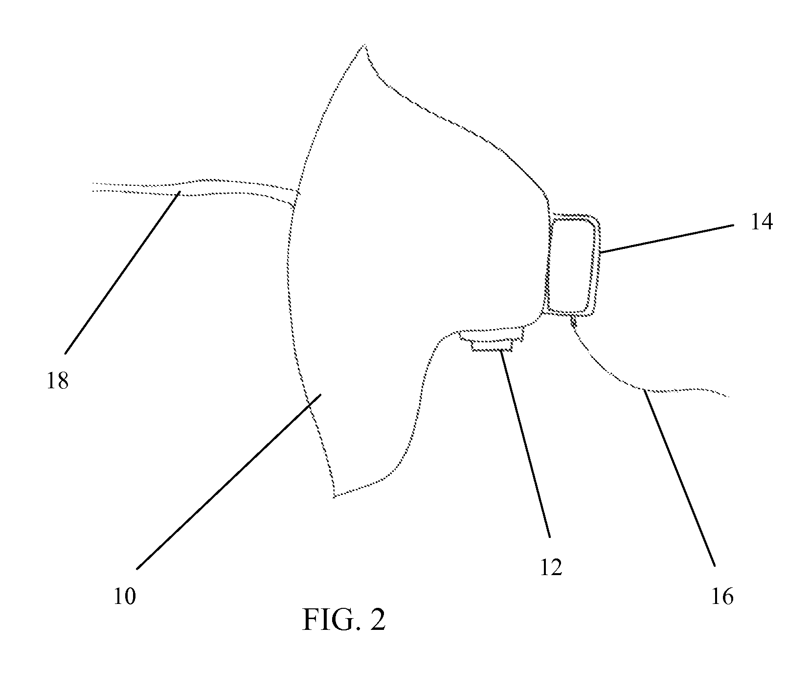
[0017]With reference now to the drawings, the preferred embodiment of the dental devices is herein described. It should be noted that the articles “a”, “an” and “the”, as used in this specification, include plural referents unless the content clearly dictates otherwise. As shown in FIGS. 1 and 5, the monitor according to the present invention comprises a breathing sensor 14 that is inserted into the mask 10 of a patient 1 and is operably connected 16 to a monitor 26. A standard oxygen mask 10, shown in FIG. 2, has means for securing the mask 10 on the patient 18 and an inlet 12 for oxygen connection. Oxygen is usually delivered through a tube 20 (shown in FIG. 3) attached to the inlet 12. Often, medication is introduced into the oxygen flow through an atomizer 22, shown in FIG. 4, connected in line with the inlet 12 and tube 20.

[0018]The breathing improvement monitor is designed to constantly measure the ratio of the pulmonary flow to the respiration rate as a function of time. The ...


PUM

PropertyMeasurementUnit
currentaaaaaaaaaa
respiration rateaaaaaaaaaa
timeaaaaaaaaaa

Abstract

The present invention is a breathing improvement monitor that continuously measures involuntary breathing. The monitor is a sensor apparatus that is attached to a patient's mask which is connected to the monitoring apparatus. The sensor may be reusable and attachable and detachable to a mask or it may be an integral part of a breathing mask. The sensor technology may be any type sufficient in the art, including but not limited to solid state sensors, transducers, electromagnetic microturbines and the like. Since the mask does not have to be removed and the sensor provides constant signal to the monitoring apparatus, a real time status of a patient's involuntary breathing capability may be determined for a doctor's consideration.

Description

FIELD OF THE INVENTION[0001]The present invention relates to the field of medical monitors and more particularly relates to a monitor, attachable to a breathing assistance mask, to measure improvement in involuntary breathing.BACKGROUND OF INVENTION[0002]There have been designed and created many devices to aid in the breathing of patients with impaired lungs. Some patients have sufficient breathing impairment such that they need a respiratory device that actually breathes for them. Others use oxygen masks and tubes that are designed only to supplement the oxygen intake for patients who have breathing impairment yet is still able to breathe on their own. Some of these devices are designed with an internal atomizer with the purpose of delivering a medication to the lungs of a patient in the form of an aerosol. A patient with impaired breathing can thus be given a constant supply of supplemental oxygen while at the same time be given life saving medications in an aerosol form through t...

Claims


Application Information

Patent Timeline
Patent Type & Authority Patents(United States)
IPC IPC(8): A62B7/10G01D21/00G01L7/00A62B7/04A62B7/00A62B18/02A62B19/00
CPCA61M16/06A61M16/14A61M11/00A61M16/0683A61M2230/42A61M2016/0042A61M2202/0208
Inventor JENSEN, STEVEN D
Owner CAO GROUP
Learn More