Stent coating apparatus and method

a technology of coating apparatus and stent, which is applied in the direction of packaging goods, pharmaceutical containers, packaged foodstuffs, etc., can solve the problems of coating cracking or breaking away, coating may crack along the interface between the stent and the balloon, and a portion of the coating may break away from the stent itsel

Inactive Publication Date: 2010-06-29
BOSTON SCI SCIMED INC
View PDF22 Cites 6 Cited by
  • Summary
  • Abstract
  • Description
  • Claims
  • Application Information

AI Technical Summary

Benefits of technology

[0025]There is also provided according to the teachings of the present invention, a method for coating a stent with a medication, the stent being mounted on a balloon on a catheter, the method comprising the steps of (a) providing an applicator device for dispensing a plurality of droplets of the medication on to the stent; and (b) applying the droplets with the applicator device around the stent, the droplets being large enough to prevent the balloon from becoming coated with the medication.

Problems solved by technology

This may result in depositing coating material on surfaces on which the coating is unwanted or undesirable.
Further, the coating may crack or break away when the implantable device is removed from the implantation apparatus.
As the balloon is inflated and the stent is expanded into position, the coating may crack along the interface between the stent and the balloon.
These cracks may lead to a breaking away of a portion of the coating from the stent itself.
This, in turn, may affect the medicinal effectiveness of the coating, and negatively affect the entire medical procedure.
This type of procedure using current device may, however, require providing complex data files, such as a CAD image of the device to be coated, and insuring that the device be installed in the coating apparatus in a precise manner so as to be oriented exactly the same as the CAD image.
Due to cost considerations of the system, the print head as well as the other elements of the system are not disposable.
Therefore, the system needs to be a large “tabletop” system which is typically not portable.
If the system were miniaturized sufficiently to be portable, there would be an additional risk of the device being used in the wrong orientation which would compromise operation of the print head and could thus adversely impact the coating quality.

Method used


Image

  • Stent coating apparatus and method
  • Stent coating apparatus and method
  • Stent coating apparatus and method

Examples


Embodiment Construction

[0038]The present invention is a stent coating system and method of operation thereof.

[0039]The principles and operation of a stent coating system according to the present invention may be better understood with reference to the drawings and the accompanying description.

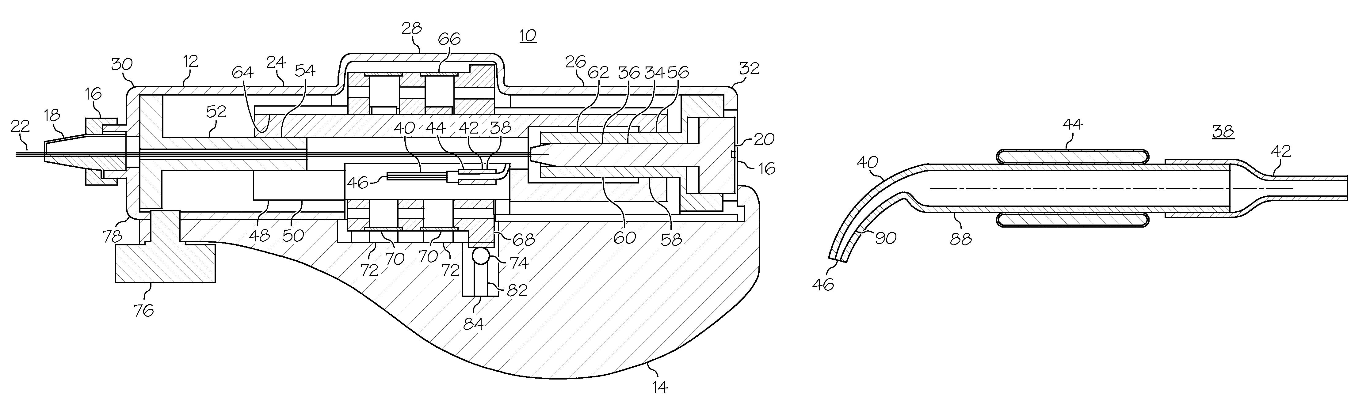
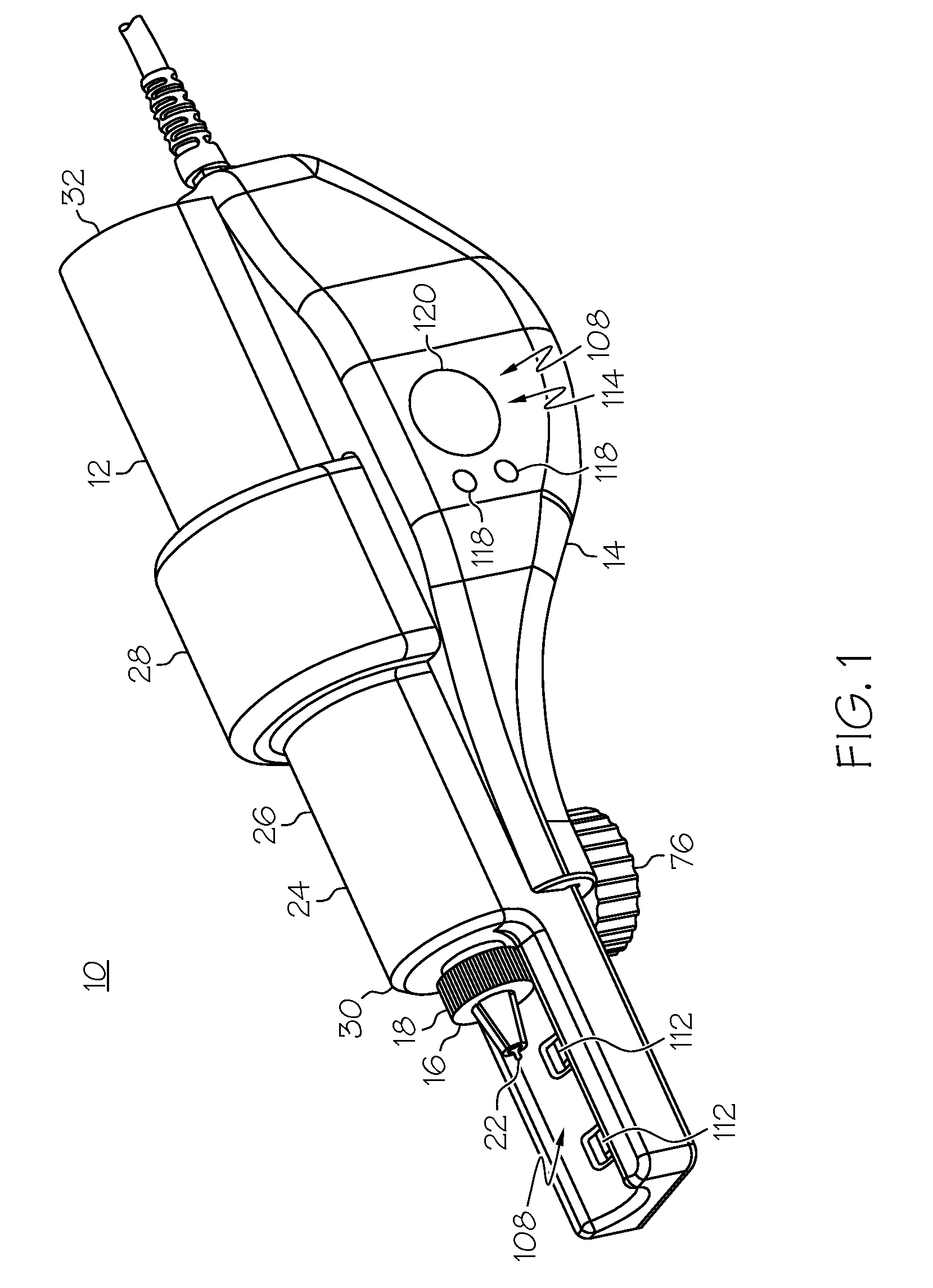
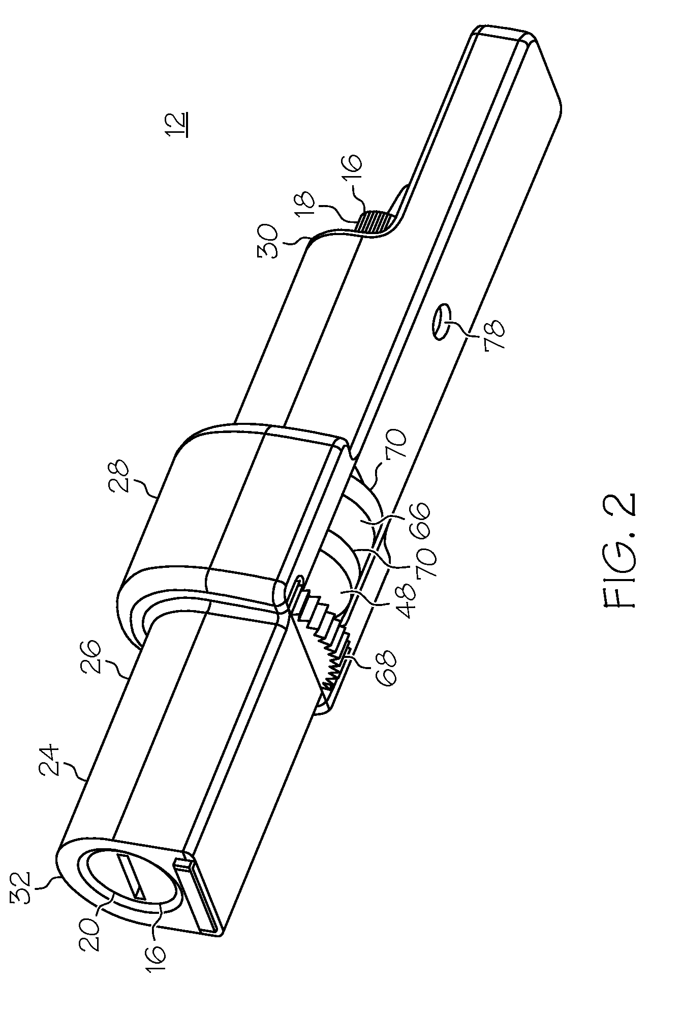
[0040]Reference is now made to FIGS. 1 to 5c. FIG. 1 is an isometric view of a stent coating system 10 that is constructed and operable in accordance with a preferred embodiment of the present invention FIG. 2 is an isometric view of a cartridge 12 of system 10 of FIG. 1, showing the rear and base of cartridge 12. FIG. 3 is an isometric view of a reusable drive unit 14 of system 10 of FIG. 1. FIG. 4a is an isometric view of system 10 of FIG. 1 having most of reusable drive unit 14 cut-away for clarity. FIG. 4b is an isometric view of system 10 of FIG. 1 having most of cartridge 12 cut-away for clarity. FIG. 5a is a plan view of system 10 of FIG. 1. FIG. 5b is a cross-sectional view along the line A-A of FIG. 5a. FIG....


PUM


Abstract

A coating system for coating a stent with a medication, the stent being mounted on a balloon on a catheter, the system having an applicator device including a fluid ejection nozzle, a reservoir and a pressure wave actuating arrangement. The nozzle has an opening configured for dispensing the medication on to the stent. The reservoir is in fluid communication with the nozzle. The nozzle and the reservoir are configured for generating a negative pressure for preventing leakage of the medication via the opening. The pressure wave actuating arrangement is configured for generating a pressure wave in the nozzle for causing fluid displacement in the nozzle, thereby ejecting a droplet of the medication from the opening. The negative pressure of the nozzle and the reservoir are configured in order that the remaining medication is drawn toward the opening to replace the medication dispensed with the droplet.

Description

CROSS REFERENCE RELATED APPLICATIONS[0001]This application is a continuation of international application number PCT / IL2004 / 000720, filed 4 Aug. 2004, which claims the priority of U.S. Provisional Application No. 60 / 491,977, filed 4 Aug. 2003 the contents of all of which are incorporated herein by referenceFIELD AND BACKGROUND OF THE INVENTION[0002]The present invention relates to the coating of medical devices intended for in vivo deployment and, in particular, it concerns a method and device, which is suitable for use in an operating theater just prior to implantation, for selectively applying a medical coating to an implantable medical device, for example a stent.[0003]The practice of coating implantable medical devices with a synthetic or biological active or inactive agent is known. Numerous processes have been proposed for the application of such a coating. Soaking or dipping the implantable device in a bath of liquid medication is suggested by U.S. Pat. No. 5,922,393 to Jayar...

Claims


Application Information

Patent Timeline
Patent Type & Authority Patents(United States)
IPC IPC(8): B05B7/00B05B3/00B05C11/00B41J2/045A61JA62C13/62B05B1/08B05B3/04B05B17/04B05D3/00
CPCB05B13/04B05B13/0426B05B17/0607B05B13/0436B05B13/0421B05B13/02B05B15/12B05B16/00
Inventor SHEKALIM, AVRAHAM
Owner BOSTON SCI SCIMED INC
Why Eureka
Try Eureka