Implantable medical lead designs

a technology of medical leads and implants, applied in the field of medical devices, can solve the problems of affecting the shape of the medical, affecting the ability to adequately anchor the tip of the medical in the tissue, and the removal of the patient is much more traumatic, so as to improve the stiffness of the medical lead, improve the stiffness, and reduce the impact of bending stress

Inactive Publication Date: 2011-08-30
MEDTRONIC INC
View PDF93 Cites 39 Cited by
  • Summary
  • Abstract
  • Description
  • Claims
  • Application Information

AI Technical Summary

Benefits of technology

[0009]In another embodiment, the invention provides a medical lead having semi-conical shaped distal tip that becomes wider at more distal tip locations. In other words, the distal tip tapers radially outward. Semi-conical distal tip features may find uses in a variety of lead applications, including specific applications in which the lead assumes a J-shaped distal region for implantation in a patient's right atrium. The semi-conical shaped tip may provide a structure that allows fibrous tissue growth to anchor the lead, but may be less aggressive than conventional tines, allowing removal without substantial tissue mutilation. Moreover, the semi-conical shape may harness an inherent spring force of a J-shaped lead configuration such that an axial force component of forces that counterbalance the inherent spring force can be used to force the lead tip against tissue of a patient's atrium.
[0011]In other embodiments the invention may be directed to an implantable medical device (IMD) including a housing to house circuitry, and a medical lead electrically coupled to the circuitry. The medical lead may include the features mentioned above, such as first and second coiled portions to allow for variable stiffness of a first portion relative to a second portion, or a semi-conical shaped distal tip to improve fixation of the lead tip to tissue and possibly harness spring forces in a useful way. In some cases, the lead may include both the first and second coiled portions to allow for variable stiffness, and the semi-conical shaped distal tip to improve tissue fixation.
[0014]The different embodiments may be capable of providing a number of advantages. For example, the use of a varying number of filars in a lead coil at selected positions along the length of a medical lead can improve stiffness characteristics of medical leads. Moreover, the use of a varying number of filars in a lead coil can achieve improved stiffness with less impact on bending stress on the filars in the lead. In other words, varying the number of filars can be used to increase stiffness without making bending stress to filars of the lead unacceptable for certain applications. Such features may be particularly useful for leads designed to assume a J-shape following implantation, but may be advantageous in numerous other applications as well.
[0015]The semi-conical distal tip features can provide advantages in terms of improved tissue fixation to the lead, e.g., by fibrous tissue growth around the tip, and may also be useful in harnessing spring forces to force the lead tip against tissue. Moreover, a semi-conical distal tip may be removable from fibrous tissue with significantly less trauma to a patient than the removal of lead tips that include tines. In some cases, the semi-conical distal tip may be designed such that the conical shape increases in thickness by no more than 25 percent, which may ensure that removal can be made without substantial tissue mutilation. Instead, the tissue may stretch, allowing removal of the lead with reduced trauma relative to lead tips that include tines.

Problems solved by technology

A number of challenges exist with respect to medical leads.
Stiffness characteristics of the medical lead may affect the ability to achieve such a desired shape, however, and may also affect the shape of the medical lead following removal of the stylet.
Tissue fixation is another challenge relating to medical leads.
Distal tines, however, make lead removal much more traumatic to a patient because the tines can cause significant tissue damage upon removal from tissue.
Moreover, the ability to adequately anchor a lead tip in tissue can also be complicated when the lead assumes different shapes, such as a J-shaped distal tip.

Method used


Image

  • Implantable medical lead designs
  • Implantable medical lead designs
  • Implantable medical lead designs

Examples


Embodiment Construction

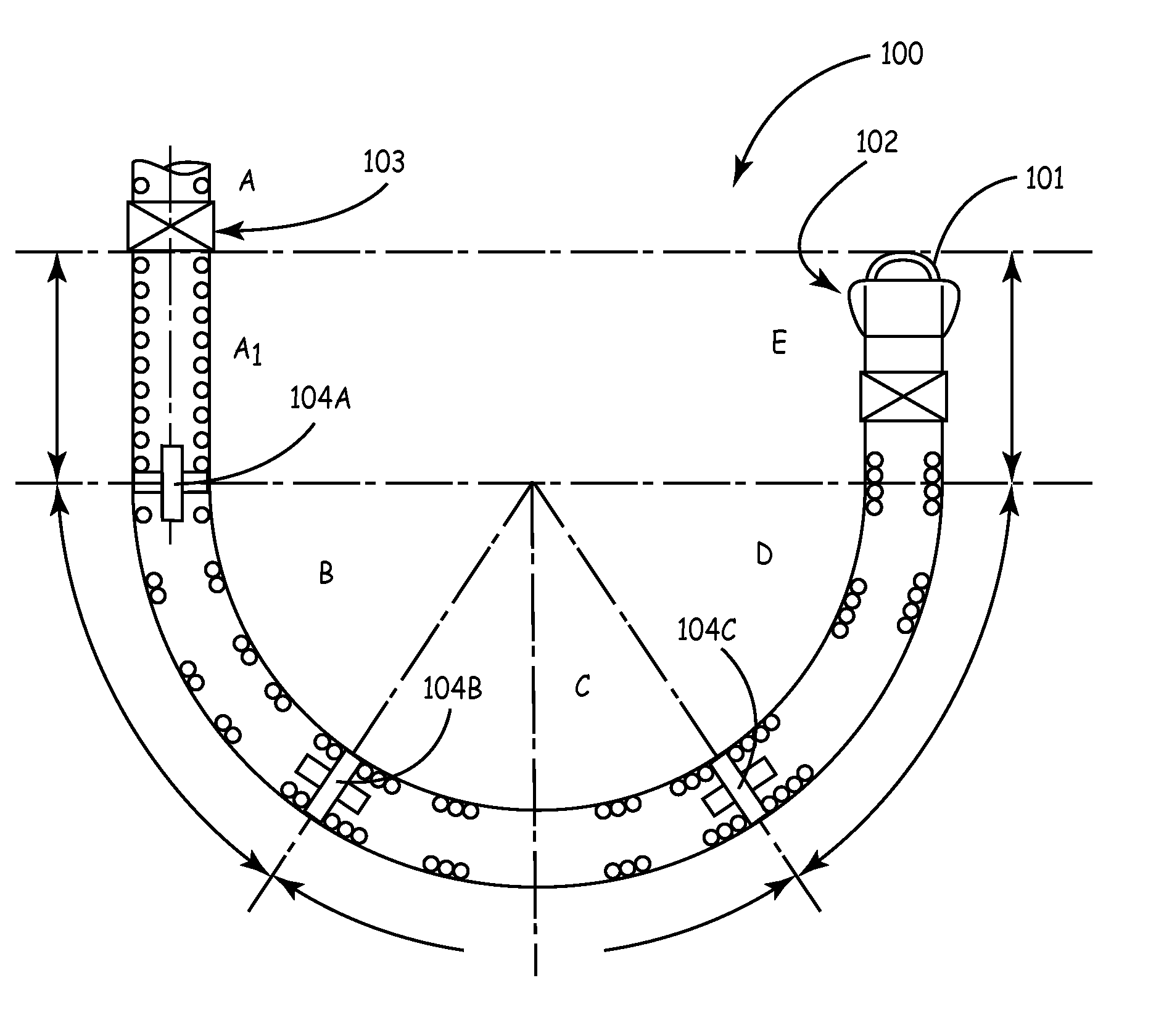
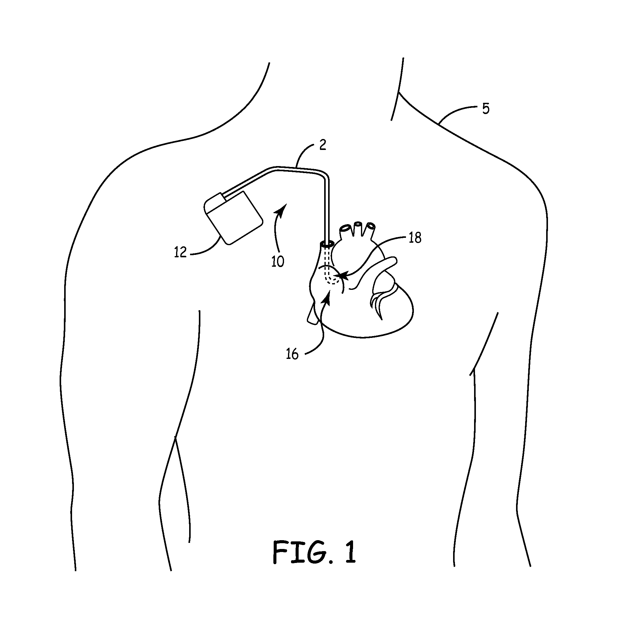
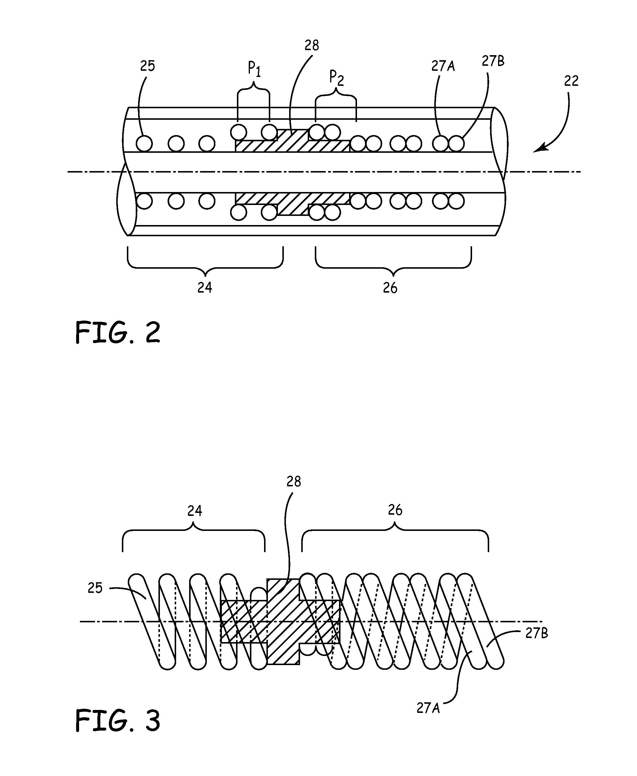
[0030]The invention is directed to medical leads for use in implantable medical devices. Various features of medical leads are described, many of which may be useful in a variety of different leads used for a variety of different applications. In one embodiment, the invention provides a medical lead of varying stiffness characteristics. In another embodiment, the invention provides a medical lead having a semi-conical shaped distal tip that becomes wider at more distal tip locations. In other words, the distal tip tapers radially outward. The distal tip may be semi-concial in that it takes a form that corresponds to a portion of a cone. These and other embodiments described herein may be used to improve medical leads for a wide variety of applications. Such applications may include specific applications in which a distal end of the lead is implanted in the roof of a patient's right atrium. When implantation in the right atrium is desired, the lead may be formed into a J-shape at a d...


PUM


Abstract

The invention is directed to medical leads for use with implantable medical devices. Various features of medical leads are described, many of which may be useful in a variety of different leads, e.g., used in a variety of different applications. In one embodiment, the invention provides a medical lead of varying stiffness characteristics. In another embodiment, the invention provides a medical lead having a semi-conical shaped distal tip that becomes wider at more distal tip locations. In either case, described lead features may be particularly useful for J-shaped lead configurations used for implantation in a patient's right atrium. Many other types of leads, however, could also benefit from various aspects of the invention.

Description

[0001]This application claims priority from U.S. Provisional Application Ser. No. 60 / 422,955, filed Oct. 31, 2002, the entire content of which is incorporated herein by reference.FIELD OF THE INVENTION[0002]The invention relates to medical devices and, more particularly, to implantable medical leads for use with implantable medical devices (IMDs).BACKGROUND OF THE INVENTION[0003]In the medical field, implantable leads are used with a wide variety of medical devices. For example, implantable leads are commonly used to form part of implantable cardiac pacemakers that provide therapeutic stimulation to the heart by delivering pacing, cardioversion or defibrillation pulses. The pulses can be delivered to the heart via electrodes disposed on the leads, e.g., typically near distal ends of the leads. In that case, the leads may position the electrodes with respect to various cardiac locations so that the pacemaker can deliver pulses to the appropriate locations. Leads are also used for sen...

Claims


Application Information

Patent Timeline
Patent Type & Authority Patents(United States)
IPC IPC(8): A61N1/05
CPCA61N1/0534A61N1/0539A61N1/0551A61N1/0565
Inventor SMITS, KAREL F. A. A.RUTTEN, JEAN J. G.ADAMS, PAUL G.
Owner MEDTRONIC INC
Why Eureka
Try Eureka