Deck fastener and method of use

a technology of fasteners and clips, applied in the direction of snap fasteners, hose connections, building repairs, etc., can solve problems such as system hidden, and achieve the effect of convenient installation

Active Publication Date: 2011-09-06
PAN AMERICAN SCREW
View PDF36 Cites 74 Cited by
  • Summary
  • Abstract
  • Description
  • Claims
  • Application Information

AI Technical Summary

Benefits of technology

[0007]An object of the invention is that the decking members are easy to install. This is especially true with regards to decks that are situated close to the ground and have limited access to the underside of the decking members. With this system, there is no need to access the underside of the decking members for installation or maintenance. With this system there is no requirement to use any fastening means that penetrate any surface of the decking member.
[0009]Additionally, the invention facilitates straightforward installation and maintenance because the embodiments position and maintain the proper spacing among the decking members and between the decking member and the joist. This eliminates the need to use spacers during installation. Moreover, the person installing or maintaining the decking members will not have to use a hammer to strike any part of the decking members.
[0010]Since the proper spacing of the decking members is maintained at all times, the invention promotes appropriate aeration around the decking members. The proper spacing that promotes appropriate aeration is maintained between both the multiple decking members and between the decking members and the joists. Appropriate aeration helps maintain low levels of mold and fungus growth on the decking members.

Problems solved by technology

This is especially true with regards to decks that are situated close to the ground and have limited access to the underside of the decking members.
Furthermore, the system is hidden because no part of the fasteners is seen from the decking surface.

Method used


Image

  • Deck fastener and method of use
  • Deck fastener and method of use
  • Deck fastener and method of use

Examples


Embodiment Construction

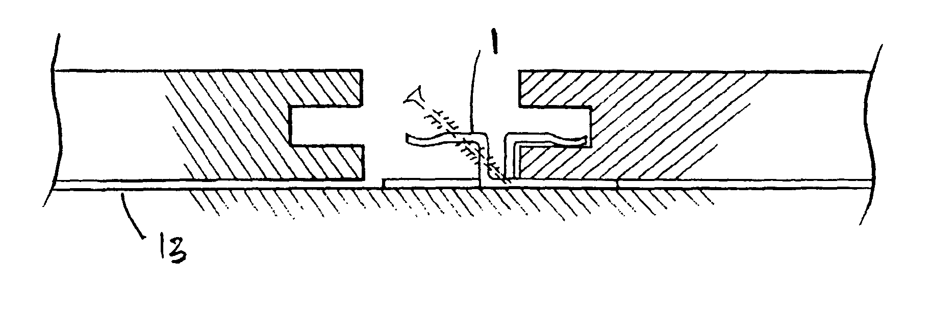
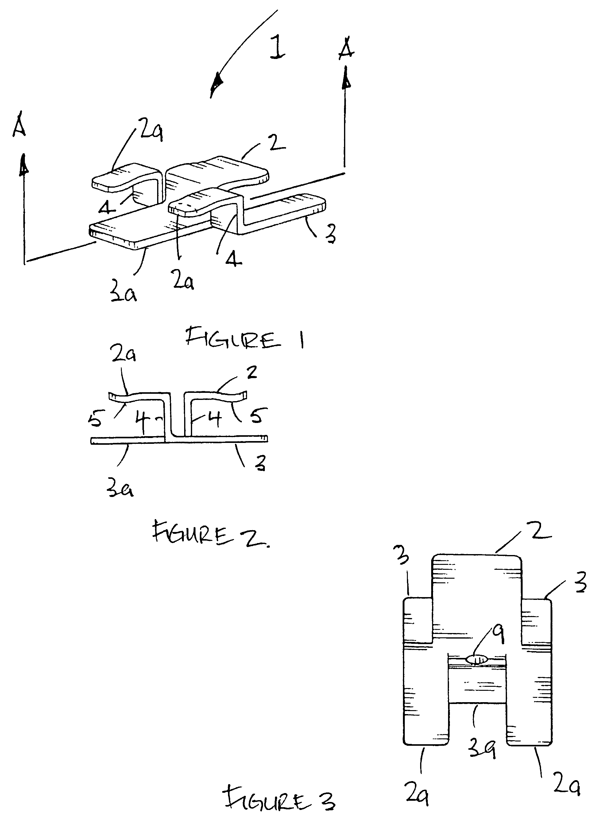
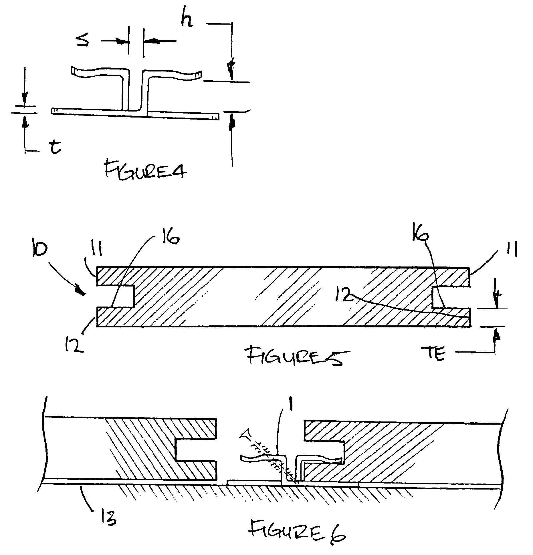
[0023]Referring to FIG. 1, a unitary clip 1 according to this invention is illustrated. The clip is intended to be used in conjunction with a deck member or plank which is manufactured with longitudinal grooves or slots 10 in each opposing end as shown in FIG. 5. In use, the clip is securely fastened to the surface of a supporting deck surface such as a joist member and serves as an anchoring device to secure the decking members.

[0024]The grooves 10 function to receive the clip. Referring to FIG. 5, the groove or slot 10 in the side edge of the decking member forms a top edge 11 and a bottom edge 12. The thickness of the bottom edge TE of the decking member is sized to be slightly larger than the arm flange height h of the clip shown in FIG. 4 as will be hereafter described. This method of installing decking members is especially useful for more expensive decking members manufactured from non-wood, PVC or composite materials. Traditional wood decking members may also be used.

[0025]R...


PUM


Abstract

A clip device for fastening first and second structural members typically decking members. The clip device has a base portion with first and second opposed ends and a thickness a first vertical leg portion integral with the leg base portion is horizontally spaced apart from a second vertical leg portion integral with the base portion. Arm flange portions integral to the first and second vertical leg portions are horizontally spaced from the base and aligned respectively towards said first and second opposed ends. A fastener receiving hole in the base is used to attach the clip device to the joist. The base portion, vertical leg portion and arm flange portion define diametrically opposed U-shaped jaw elements for holding the structural member to the joist.

Description

TECHNICAL FIELD[0001]The invention relates to an under deck fastening system and method, in addition, to a deck fastener clip which can be used to “invisibly” attach a deck board to a supporting joist-like structure.BACKGROUND OF THE ART[0002]There are a variety of decking systems on the market today. Most of the decking systems utilize some sort of fastening means such as a screw, nail or staple to attach the decking members to the underlying joists. Furthermore, with most decking systems, the fastening means is installed directly through the top face of the decking members to the joist below. However, these decking systems have some major drawbacks.[0003]The common method of securing the decking members to the underlying joists by directly fastening the decking member to the joist through the top face of the decking member has many drawbacks. First, the fastening means are visible and this leads to many shortcomings. The heads of the fastening means are unattractive and take away ...

Claims


Application Information

Patent Timeline
Patent Type & Authority Patents(United States)
IPC IPC(8): E04F15/04E04B5/00E04B1/38
CPCE04F15/02Y10T24/307Y10T24/3431E04F2201/0517E04F2015/02122
Inventor ORCHARD, BRIAN KEITH
Owner PAN AMERICAN SCREW
Why Eureka
Try Eureka