Cartridge-based air gun

a technology of air guns and cartridges, applied in the field of cartridge-based air guns, can solve the problems of cartridges that cannot be ejected either, slide does not perform a blowback operation, and cannot eject cartridges with mechanisms similar to those of real guns, so as to accelerate the rearward movement time of the cylinder, perform the blowback operation quickly, and stable loading to the chamber

Inactive Publication Date: 2011-09-06
MARUSHIN IND
View PDF27 Cites 10 Cited by
  • Summary
  • Abstract
  • Description
  • Claims
  • Application Information

AI Technical Summary

Benefits of technology

[0013]In addition, an object of the present invention is to provide the above-mentioned cartridge-based air gun wherein faster execution of the blowback operation is made possible.
[0014]Further, an object of the present invention is to provide the above-mentioned cartridge-based air gun wherein an operation for loading a cartridge from a clip of a magazine to the chamber is performed smoothly and reliably.
[0016]Further, a cartridge-based air gun according to a second aspect of the present invention is a cartridge-based air gun wherein, by providing a gap of at least 1 mm between a rear end of the cylinder and a rubber packing provided on an outer circumference of a front end of a piston, blowback of the slide is performed quickly by discharging at once through the gap the gas that fills the cylinder.
[0022]Further, with respect to the above-mentioned blowback operation, it had been conventional to provide a gap of about 0.5 mm between the rear end of the cylinder and the rubber packing provided on the outer circumference of the front end of the piston, and to thus discharge from that gap the compressed gas that fills the interior of the cylinder. However, the blowback operation of the slide cannot be performed quickly with a gap of such a size. With a cartridge-based air gun according to the second aspect of the present invention, by providing the gap of at least 1 mm between the rear end of the cylinder and the rubber packing provided on the outer circumference of the front end of the piston, the gas that fills the interior of the cylinder is discharged at once from that gap, thereby expediting the rearward movement time of the cylinder, and making it possible to perform the blowback operation quickly.
[0023]Further, in a cartridge-based air gun according to the third aspect of the present invention, by virtue of the fact that the notch portion provided in the upper end of the front wall of the body of the magazine has such a depth that allows for forward movement of the uppermost cartridge in the clip, the uppermost cartridge in the clip moves in the forward direction and it becomes possible to place the front end of the cartridge in contact with the inclined guiding surface of the feeding ramp provided at a forward position relative to the magazine. In addition, the length of the magazine lips is so formed that the engaging action of the magazine lips with respect to the cartridge can be released at the same time as the front end of the cartridge thus comes into contact with the inclined guiding surface of the feeding ramp. Consequently, instead of having the cartridge disengage from the magazine lips in an inclined state, it is possible to have the cartridge hit the ceiling of the chamber in a substantially parallel state, thereby enabling stable loading to the chamber.

Problems solved by technology

However, there had yet to be developed an air gun wherein a clip loaded with a plurality of cartridges and a gas reservoir are integrally constructed within a magazine, this magazine is detachably loaded in a magazine chamber in the body of the gun, and the above-mentioned blowback and ejection of the cartridge are performed after a bullet is fired.
However, in the case of toy guns which fire BB bullets or resin bullets within cartridges using compressed gas, it was impossible to eject cartridges with mechanisms similar to those of real guns.
As a result, the slide does not perform a blowback operation, and the cartridge cannot be ejected either.

Method used


Image

  • Cartridge-based air gun
  • Cartridge-based air gun
  • Cartridge-based air gun

Examples


Embodiment Construction

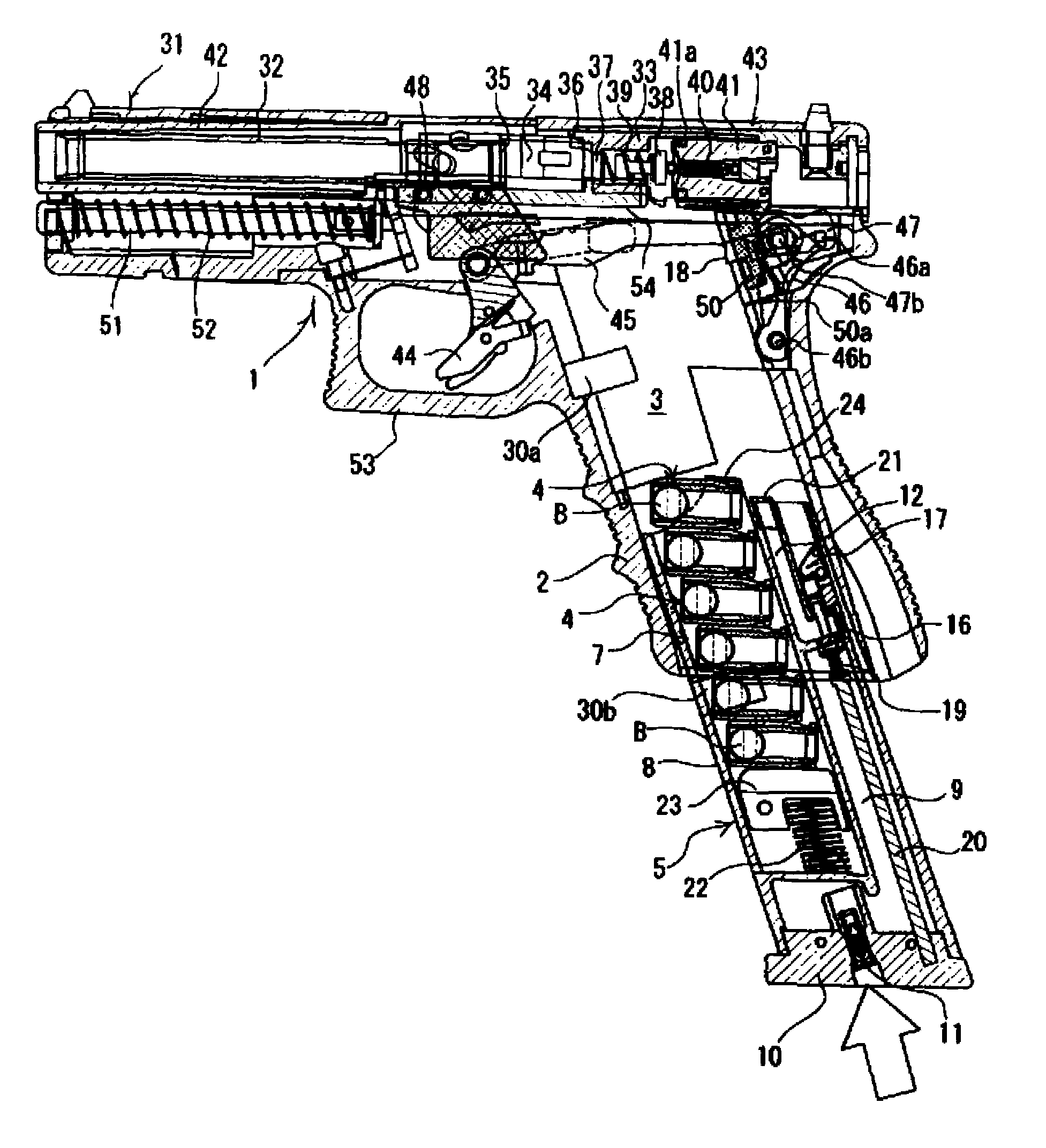
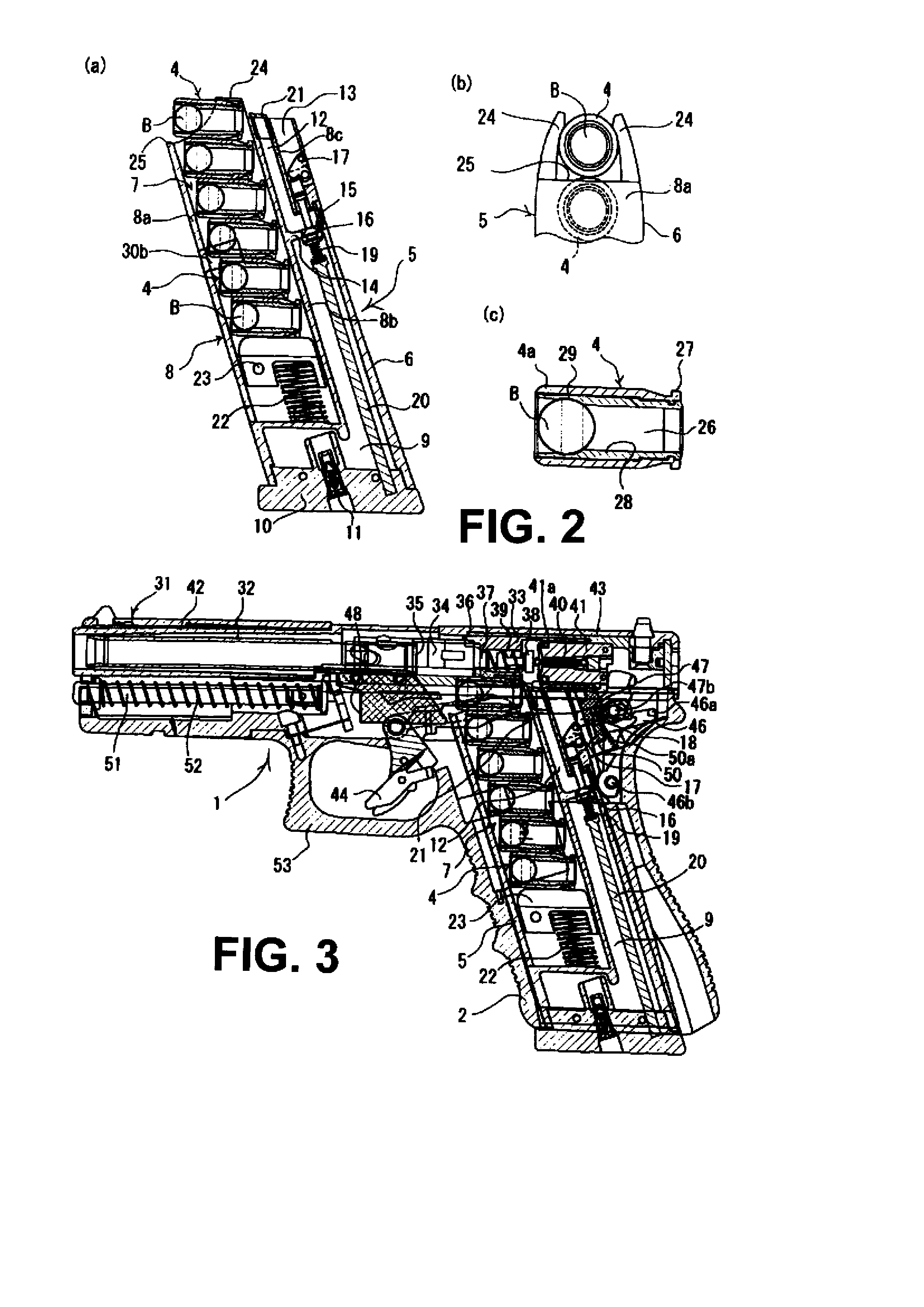
[0038]An embodiment of the present invention is described below with reference to the drawings. It is noted that the terms “forward” and “rearward” as used herein in describing the present invention respectively refer to the muzzle side and the hammer side of the body of the gun.

[0039]First, the overall structure of an air gun according to the present invention will be described. The air gun shown in FIG. 1 is one in which a magazine 5, which is separate from a gun body 1, is detachably loadable from a lower opening in a magazine chamber 3 provided in a grip 2 of the gun body 1.

[0040]As shown in FIG. 2(a), the magazine 5 comprises a clip 7 and a gas reservoir 9 that are integrally constructed in a magazine body 6. In other words, its structure is such that the clip 7 and the gas reservoir 9 are partitioned with a center boundary wall 8b, dividing the interior of the magazine body 6 into front and rear areas. However, the gas reservoir 9 is so formed as to wrap around under the lower...


PUM


Abstract

A cartridge-based air gun that fires a BB bullet or a resin bullet inside a cartridge using compressed gas, includes an engaging structure of an extractor that enables blowback and the automatic ejection of the cartridge. An extractor, which engages with a rim that is formed at the rear end of a cartridge loaded in a chamber, is pivotally provided on a side portion of a cylinder so as to be rotatable. A claw portion formed at the tip of the extractor engages with the rim of the cartridge by the urging force of a spring provided between the extractor and the cylinder. A slide moves rearward while the cartridge is held inside the chamber. As the cylinder moves rearward with the stopping of the supply of compressed gas from a gas reservoir, the cartridge comes into contact with an ejector, is released from the engagement by the extractor, and is ejected from the chamber.

Description

BACKGROUND OF THE INVENTION[0001]1. Field of the Invention[0002]The present invention relates to cartridge-based air guns in which after a bullet inside a cartridge has been fired by means of compressed gas, the slide automatically moves forward / rearward, and the spent cartridge is automatically ejected.[0003]2. Background Art[0004]Air guns in which plastic bullets (so-called “BB bullets”) or resin bullets are fired by means of compressed gas have conventionally been known. In addition, cartridge-ejecting air guns in which after a bullet loaded in a cartridge has been fired, the slide automatically moves forward / rearward (so-called “blowback”) and the spent cartridge can be ejected have been developed.[0005]However, there had yet to be developed an air gun wherein a clip loaded with a plurality of cartridges and a gas reservoir are integrally constructed within a magazine, this magazine is detachably loaded in a magazine chamber in the body of the gun, and the above-mentioned blowba...

Claims


Application Information

Patent Timeline
Patent Type & Authority Patents(United States)
IPC IPC(8): F41B11/00A63H33/18F41B11/56F41B11/62F41B11/68F41B11/723
CPCF41B11/55F41B11/62F42B8/02F42B6/10F42B5/145
Inventor KAWASHIMA, HIROSHI
Owner MARUSHIN IND
Why Eureka
Try Eureka