Automated drill string position survey

a drill string position and automatic technology, applied in the direction of survey, directional drilling, borehole/well accessories, etc., can solve the problems of inability to use survey tools in real time with top hammer drills, increase in the number of joints, and decrease in the accuracy of drilling processes

Inactive Publication Date: 2011-09-06
CMTE DEV LTD
View PDF20 Cites 17 Cited by
  • Summary
  • Abstract
  • Description
  • Claims
  • Application Information

AI Technical Summary

Problems solved by technology

If the pattern of long holes deviates from the desired plan this can result in dilution of the ore body by drilling outside the design area, the creation of oversize broken rock caused by lower charge density between wandering holes, and Hanging Wall / Foot Wall damage hence stability issues through increased charge density.
As the number of rods in the hole increases, the number of joints increases and the accuracy of the drilling process diminishes.
Although technology to survey drill holes in real time (i.e. as part of the drilling operation) exists in applications where the drill string is not subject to top hammer conditions, it is not hitherto been possible to use survey tools in real time with top hammer drills due to the destructive nature of the percussive force in the drill string.
In practice this is not the case and holes may deviate significantly as their length increases.
This is a time consuming and costly task that may eventually identify hole characteristics but if deviation outside allowable constraints has occurred, then relies on significant corrective action being undertaken as a secondary or tertiary process after the top hammer drill rig has moved from the drilling site.
No real time survey technology exists that can withstand the down hole vibration and acceleration that is associated with a top hammer drill and ascertain the true path of the hole before completion and relay the data ultimately to decision making software.
In addition, many current systems, which rely on changes in the earth's magnetic field to determine position, cannot be accurately used in magnetic environments.

Method used


Image

  • Automated drill string position survey
  • Automated drill string position survey
  • Automated drill string position survey

Examples


Embodiment Construction

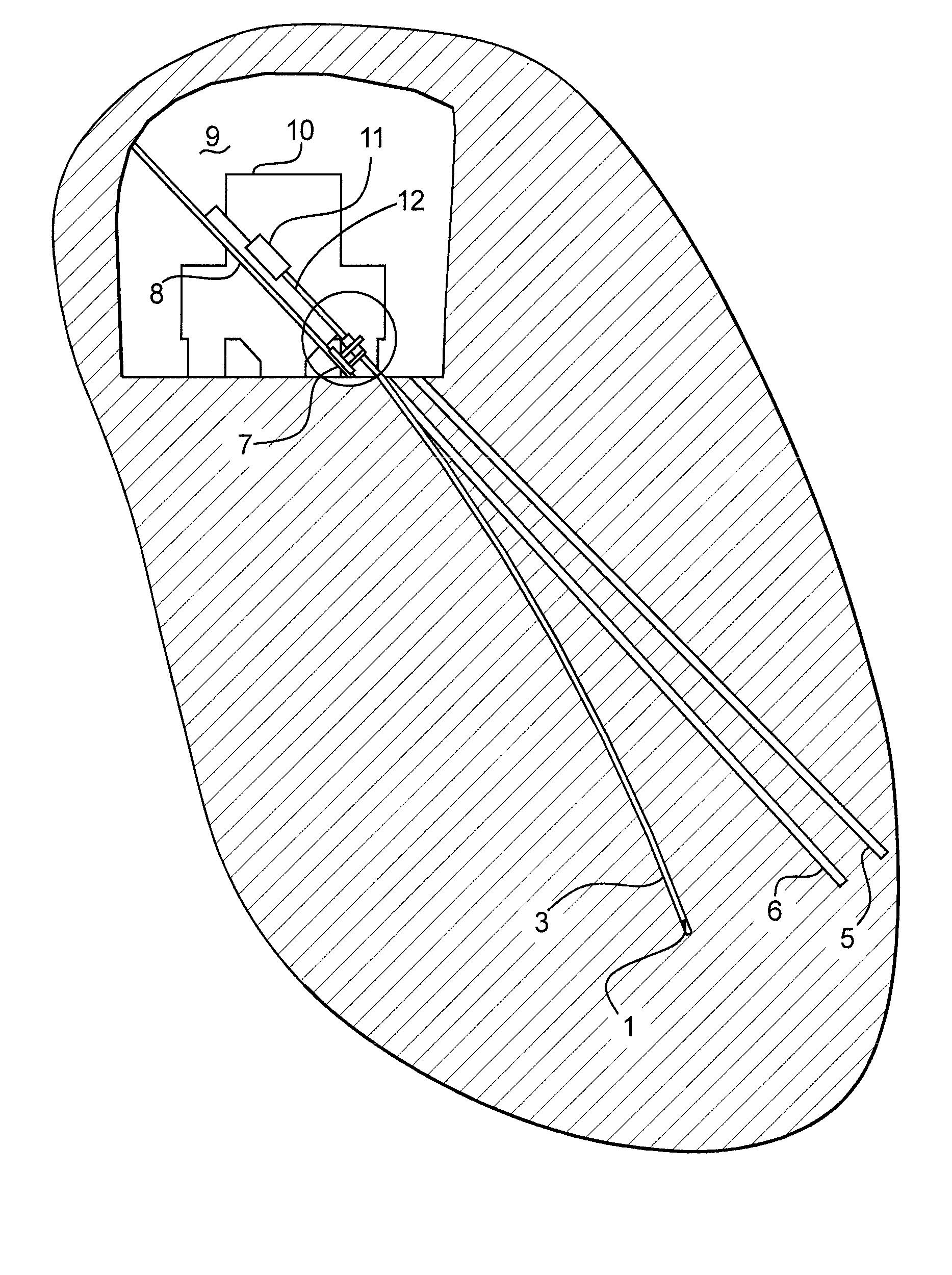
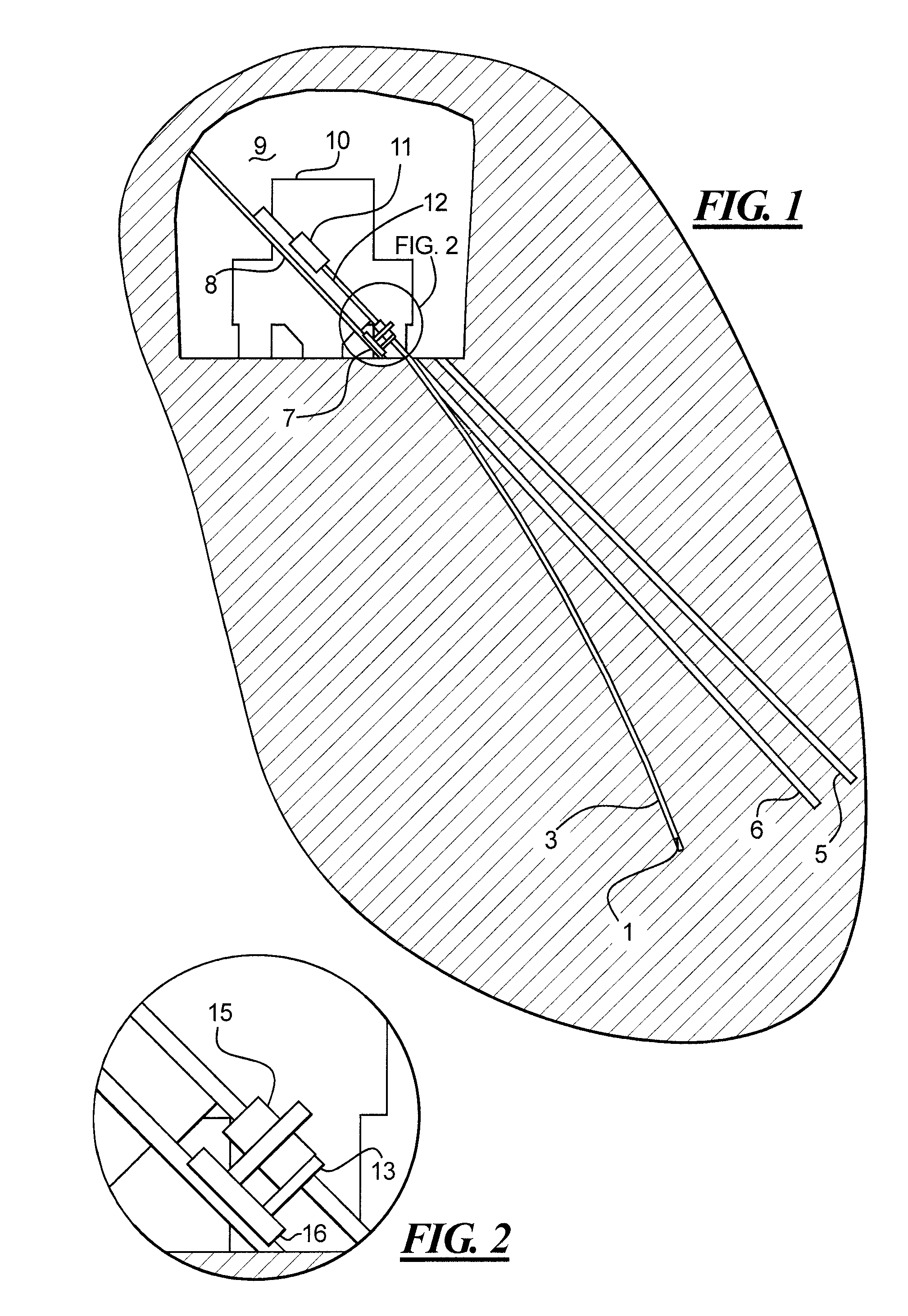
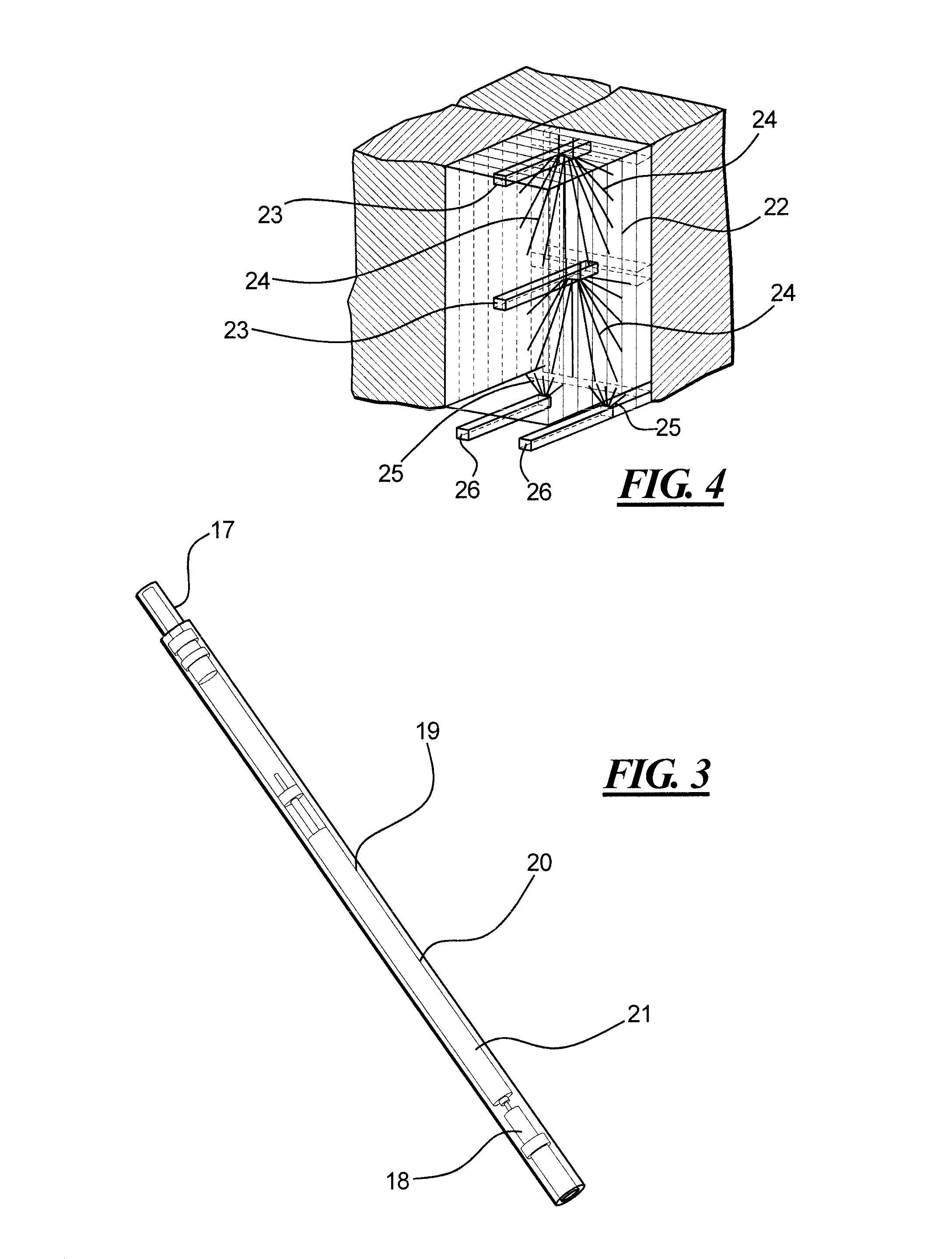
[0024]In the preferred form of the invention a top hammer drill rig 10 is positioned in an access / drill drive 9 of the type generally shown at 23 in FIG. 4 and described earlier with reference to the prior art.

[0025]The top hammer drill rig includes a hydraulic powered drifter 11 mounted on a drifter feed rail 12, typically held in place by bracing stingers 7 and 8 which brace the top hammer drill into the floor and roof respectively of the access / drill drive 9.

[0026]The top hammer drill rig is fed with drilling rods from a carousel (not shown) from where they are fed into a tool handler (not shown) and held by a clamp 13.

[0027]The rig is provided with a survey tool, described below, which can feed information to a receiver 15 mounted on an automated drill string position survey home unit 16 on the drill rig.

[0028]The drill string 3 is provided at the cutting end with a drill bit 1 described in more detail with reference to FIG. 3.

[0029]Just above the drill bit 1 there is located a ...


PUM


Abstract

A method of surveying drill holes, typically for use in underground mining situations where the holes are bored using a top hammer drill rig (10), utilizes a survey tool located adjacent the drill bit (1) which is used to log position readings as the drill string is withdrawn from the hole after the drilling operation. In this manner, it is possible to log the actual hole bored by the drill string (3) in real time as the drilling operation proceeds, and show deviation from intended hole positions (5) or (6). The survey tool typically includes an inertial survey package, a power source, and a data logger with the survey package selected from the group comprising commercially known inertial known survey packages, for superior characteristics of resistance to vibration and impact. The survey tool is maintained in a sleeping mode while drilling is undertaken, and activated to provide position data as the drill string is progressively withdrawn from the actual hole path (3).

Description

CROSS-REFERENCE TO RELATED APPLICATION[0001]This is the U.S. National Phase of International Application No. PCT / AU2005 / 000076, filed on Jan. 24, 2005 claiming priority to Australian Patent Application No 2004900298, filed on Jan. 22, 2004.FIELD OF THE INVENTION[0002]This invention relates to an automated drill string position survey and has been devised particularly though not solely to survey drill holes formed by “top hammer” drills.BACKGROUND OF THE INVENTION[0003]In many different applications for example, in underground hard rock mines, it is extremely valuable to have timely and accurate knowledge of drill hole positions. Drill holes, commonly referred to as long holes (i.e. long hole drill and blast) are typically used for the placing of explosives in mining via open stoping, sub level stoping, block caving, vertical crater retreat methods, and sub level caving. It is useful in any underground mining that requires the drilling of long holes to distribute explosives through t...

Claims


Application Information

Patent Timeline
Patent Type & Authority Patents(United States)
IPC IPC(8): E21B47/02E21B47/022E21B7/04E21D9/00
CPCE21B47/022E21D9/003E21D9/006
Inventor KENISTON, SCOTT DAVIDLEVERS, PAUL J. A.
Owner CMTE DEV LTD
Why Eureka
Try Eureka