Snap-in cable hanger clip

a technology of cable hanger and clip, which is applied in the direction of machine supports, support parts, and support accessories of scaffolds, etc., can solve the problems of crowded tunnels and towers of antennas

Active Publication Date: 2011-09-06
COMMSCOPE INC
View PDF10 Cites 56 Cited by
  • Summary
  • Abstract
  • Description
  • Claims
  • Application Information

AI Technical Summary

Benefits of technology

[0025]During mounting, the leg(s) 7 of a typical snap-in cable hanger 5 are deflected towards one another into a spring space 13 between the leg(s) 7 to enable clearance of locking barb(s) 11, projecting from a distal end 15 of each leg 7, through the mounting hole 9. Once passed through the mounting hole 9, the leg(s) 7 are allowed to spring back into a mounted configuration where each is biased outwards against the mounting hole 9 sidewall, the locking barb(s) 11 overhanging a bottom of the mounting hole 9, preventing snap-in cable hanger 5 removal.
[0027]The clip 17 has a top 19 from which at least two clip arm(s) 21 extend. At least one of the clip arm(s) 21 may be formed with a clip tab 23 proximate a distal end 15. The clip 17 is dimensioned with respect to the intended snap-in cable hanger 5 and mounting hole 9. The top 19 has a length greater than a diameter of the mounting hole 9. The clip arm(s) 21, spaced apart a distance proximate the mounting hole 9 inner diameter, may have an outer surface 25 formed with a radius of curvature mating with the inner diameter of the mounting hole 9. The clip tab(s) 23 are spaced along the clip arm(s) 21 a distance longer than a depth of the mounting hole 9 such that when the top 19 is seated against the mounting surface 27 that the mounting hole 9 is formed in, the clip tab(s) 23 extend below a bottom edge 28 of the mounting hole 9, clipping against the bottom edge to prevent removal of the clip 17 from the mounting hole 9. The clip arm(s) 21 have a thickness and / or reinforcing shoulder(s) 29 dimensioned with respect to the selected polymer material to have a deflection characteristic enabling the clip arm(s) 21 and clip tab(s) 23 to deflect inward enough to pass through the mounting hole 9 before returning to a static position with the clip tab(s) 23 overhanging the bottom edge of the mounting hole 9, retaining the clip 17 in position.
[0030]To minimize the chance of misplacing the clip 17 prior to installation, the clip 17 may be removably coupled to the snap-in hanger 5 as delivered to the installer, for example via a string, wire, tape or glue.
[0031]Failure testing of snap-in cable hanger(s) 5 installed with and without a clip 17 according to the invention has demonstrated a dramatic improvement in the load capabilities of the snap-in cable hanger(s) 5 when the clip 17 is present. One skilled in the art will recognize that the minimal additional cost of the clip 17 greatly improves the performance of the snap-in cable hanger(s) 5, without requiring extensive reinforcement and or redesign of the snap-in cable hanger(s) 5, themselves.
[0032]Although the clip 17 has been demonstrated with respect to a specific snap-in cable hanger 5 configuration, one skilled in the art will appreciate that the clip 17 may be applied according to the invention to any cable hanger configuration based upon snap-in attachment to a mounting hole 9 by deflection of leg(s) 7 or other retaining features into a spring space 13 that the clip 17 is then dimensioned to fill, preventing twisting or bending forces from biasing the leg(s) 7 or other retaining features back into the spring space 13 where disconnection and or weakening of the retention capabilities of the cable hanger can occur.

Problems solved by technology

Antenna towers and or tunnels may be crowded due to the multiplicity of signal cables and or transmission lines required for signal-carrying.

Method used


Image

  • Snap-in cable hanger clip
  • Snap-in cable hanger clip
  • Snap-in cable hanger clip

Examples


Embodiment Construction

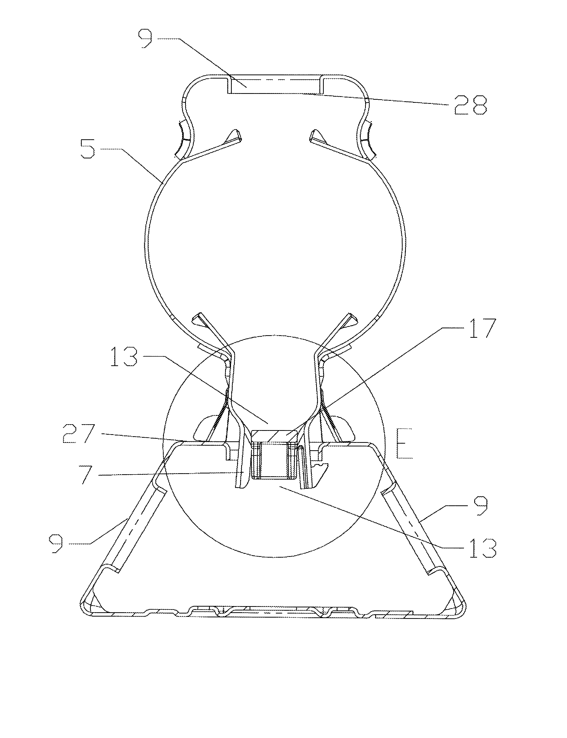
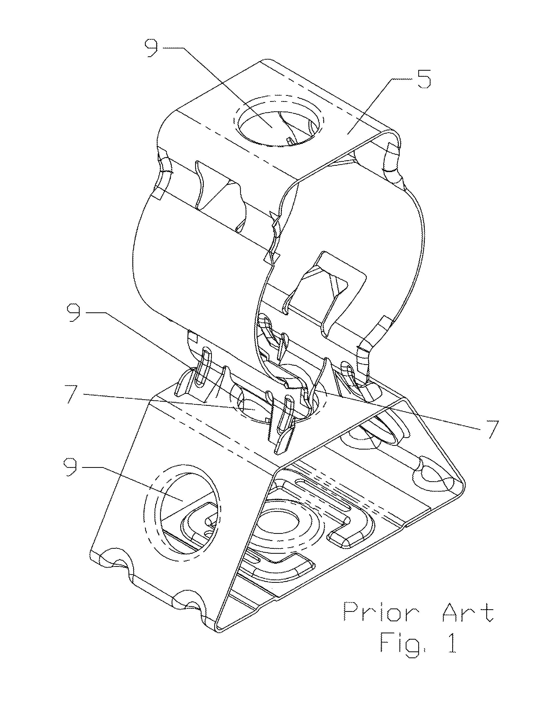
[0024]The inventor has analyzed the maximum load and failure characteristics of a snap-in cable hanger 5, for example as shown in FIG. 1. The inventor discovered that a frequent point of failure under excessive load is a twisting and or shift of the leg(s) 7 of the hanger body with respect to the mounting hole which allows retaining features of the legs, such as locking barb(s) 11, to disengage completely and or shift far enough from the seated position to where they can be deformed until they then disengage.

[0025]During mounting, the leg(s) 7 of a typical snap-in cable hanger 5 are deflected towards one another into a spring space 13 between the leg(s) 7 to enable clearance of locking barb(s) 11, projecting from a distal end 15 of each leg 7, through the mounting hole 9. Once passed through the mounting hole 9, the leg(s) 7 are allowed to spring back into a mounted configuration where each is biased outwards against the mounting hole 9 sidewall, the locking barb(s) 11 overhanging a...


PUM

PropertyMeasurementUnit
diameteraaaaaaaaaa
lengthaaaaaaaaaa
depthaaaaaaaaaa

Abstract

A clip for a snap-in cable hanger with a top from which at least two clip arm(s) extend and at least one of the clip arm(s) formed with a clip tab projecting proximate a distal end. The top having a length greater than a diameter of the mounting hole and a width dimensioned to fit within a spring space when the snap-in cable hanger is seated upon the mounting hole. The clip arm(s) spaced apart proximate the diameter of the mounting hole, having a length longer than a depth of the mounting hole.

Description

BACKGROUND OF INVENTION[0001]1. Field of the Invention[0002]This invention relates generally to devices for supporting cables and, in particular, to a clip for improving the strength characteristics of snap-in cable hangers for securing cables to support structures.[0003]2. Description of Related Art[0004]Cable hangers are used to secure signal cables and or transmission lines to support structures. Antenna towers and or tunnels may be crowded due to the multiplicity of signal cables and or transmission lines required for signal-carrying. Over time, as systems are added, upgraded and or expanded, installation of additional signal cables and transmission lines may be required. To conserve space, it is desirable for each set of cable hangers to secure more than a single cable. Certain cable hangers have been constructed to secure multiple cables; other cable hangers have a stackable construction that permits multiple cable hangers to be interlocked extending outwardly from each mounti...

Claims


Application Information

Patent Timeline
Patent Type & Authority Patents(United States)
IPC IPC(8): F16L3/22
CPCF16L3/127H02G3/30Y10T29/49863F16B21/065
Inventor KORCZAK, RICHARD
Owner COMMSCOPE INC
Why Eureka
Try Eureka