Punching tool for taking biological samples

a technology for biological samples and punching tools, which is applied in the field of punching tools for taking biological samples, can solve the problems of sample not being released from the instrument, sample not being registered into an incorrect vessel, sample not being released, etc., and achieves the effect of reducing the number of mistakes

Active Publication Date: 2011-09-06
WALLAC
View PDF7 Cites 3 Cited by
  • Summary
  • Abstract
  • Description
  • Claims
  • Application Information

AI Technical Summary

Benefits of technology

It is an object of the invention to provide a punching tool for taking biological samples that by simple means offers an instrument for use that allows carrying out an extremely safe sampling and thus considerably reducing the generation of mistakes.
The guidance channel preferably widens conically in such a manner that the cone angle ranges between 50 and 100 degrees. Such a widening improves the probability of a successful sample taking.
It is of great advantage that the smoothness of the surface in the guidance channel corresponds to a polished surface, this further assisting the sample to be released from the punching tool.
A significant advantage of the punching tool according to the invention is that it considerably reduces the number of mistakes when taking samples even though the structure thereof is simple. On account of the guidance means of the punching tool the number of mistakes has been reduced to a tenth and even much more in comparison with an instrument, in which the guidance means is not included. The guidance means also allows reducing the need to service the instrument.

Problems solved by technology

A problem with the instrument intended to be used for taking a biological sample is that the sample is not necessarily always released from the instrument.
However, a new punching does not necessarily lead to the desired result, instead each hundredth sample remains adhered to the instrument, from where it may eventually with time be released and fall into an incorrect vessel.
Such a mistake does not only decelerate sample taking but also causes the sample to be registered into an incorrect vessel, which may relate to an incorrect person or animal.
It is obvious that such a mistake may have fatal consequences.

Method used


Image

  • Punching tool for taking biological samples
  • Punching tool for taking biological samples
  • Punching tool for taking biological samples

Examples


Embodiment Construction

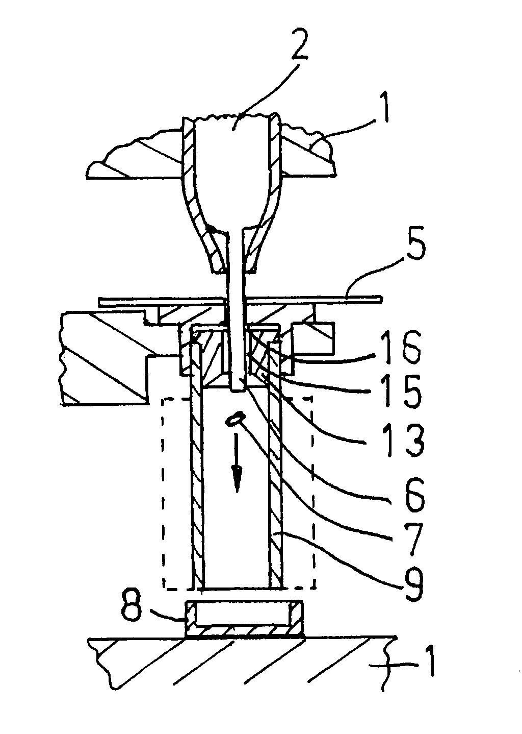
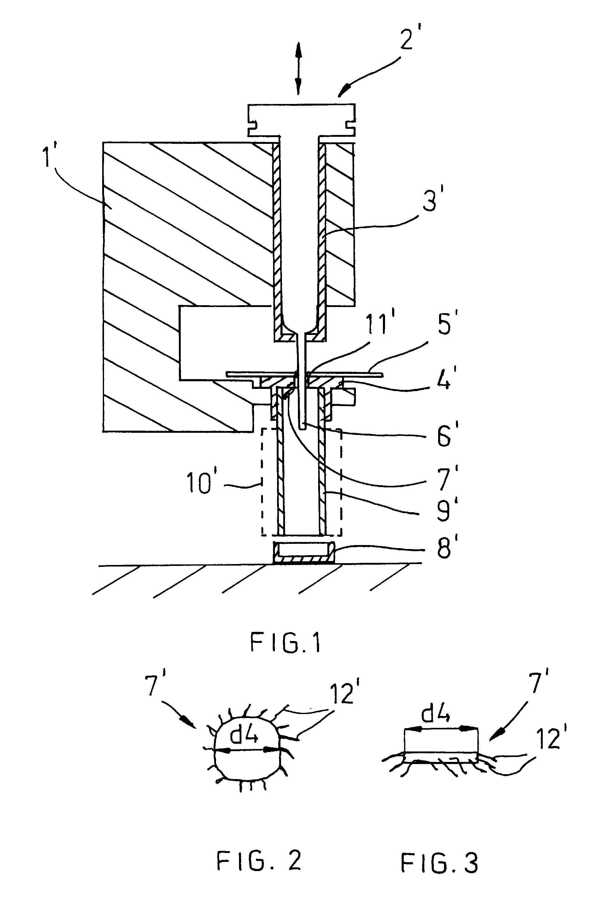
FIG. 1 shows a side view in cross section of a punching tool for taking a biological sample representing the prior art. The instrument comprises a frame 1′ and a punch supported by the frame, said punch generally being referred to with reference numeral 2′. The punch 2′ resembling a symmetric body of revolution is arranged within a tubular guidance means 3′ and to be movable upwards and downwards in respect of the latter, which is indicated by the double arrow in the Figure. In FIG. 1 the punch 2′ is in the lowest position thereof. Reference numeral 4′ refers to a die of the punching tool supported by the frame 1′. A filtering paper 5′ is placed on the upper surface of the die 4′, on which filtering paper one or more biological samples are absorbed, from which one or more samples are taken. The die 4′ comprises a punching channel 11′ that determines the size of the diameter of the sample.

In FIG. 1 the tip 6′ of the punch has punched a discoidal sample 7′ from the filtrating paper 5′...


PUM

PropertyMeasurementUnit
lengthaaaaaaaaaa
distanceaaaaaaaaaa
cone angleaaaaaaaaaa

Abstract

The invention relates to a punching tool for taking a biological sample from a filter using punching, the punching tool comprising a punch and a die provided with a punching channel for conveying the sample from the upper surface of the die towards the lower end of the die that includes a guidance means of the sample comprising a guidance channel arranged as an extension of the punching channel for receiving the sample from the punching channel, the diameter of the guidance channel is 1.02 to 2× the diameter of the punch and is greater than the diameter of the punching channel, and at the connecting point with the punching channel the guidance channel forms a shoulder and broadens towards the free end of the guidance means. In order to reduce the number of mistakes when taking samples, while the structure of the punching tool still remains simple at the end of the guidance means that faces towards the punching channel of the die, the diameter of the guidance channel is constant at a portion of the length thereof and the walls of the shoulder are placed at an angle from 170 to 300 degrees in relation to one another.

Description

BACKGROUND OF THE INVENTIONThe invention relates to a punching tool for taking a biological sample from a filter using punching, the punching tool comprising a punch and a die provided with a punching channel for conveying the sample from the upper surface of the die to the lower end of the die. More precisely, the invention relates to a punching tool also provided with a guidance means of the sample that comprises a guidance channel arranged as an extension of the punching channel for receiving the sample from the punching channel, the diameter of the guidance channel is 1.02 to 2× the diameter of the punch and is greater than the diameter of the punching channel, and at the connecting point with the punching channel the guidance channel forms a shoulder and broadens towards the free end of the guidance means. In this context the diameter of the punch naturally refers to the diameter of the cutting end of the punch.Publication DE 3942170 discloses such an instrument for taking pape...

Claims


Application Information

Patent Timeline
Patent Type & Authority Patents(United States)
IPC IPC(8): A61B10/00A61B17/14A61B17/32A61BB26F1/14G01N1/08
CPCA61B10/0045B26F1/14G01N1/08A61B17/32053G01N2001/288Y10T83/9423
Inventor LEHTINEN, KAUKO
Owner WALLAC
Why Eureka
Try Eureka