Piezoelectric power generator

a power generator and piezoelectric technology, applied in piezoelectric/electrostrictive/magnetostrictive devices, piezoelectric/electrostriction/magnetostriction machines, electrical equipment, etc., can solve the problem of low durability of piezoelectric power generators, and achieve high power generation efficiency, enhanced vibration efficiency of piezoelectric elements, and enhanced vibration efficiency

Active Publication Date: 2011-09-06
MURATA MFG CO LTD
View PDF7 Cites 8 Cited by
  • Summary
  • Abstract
  • Description
  • Claims
  • Application Information

AI Technical Summary

Benefits of technology

[0008]An object of the present invention is to provide a piezoelectric power generator whose piezoelectric plate is resistant to cracking, and which has high durability.
[0021]With the piezoelectric power generator according to the present invention, a bias compressive stress acting in the thickness direction of the piezoelectric plate is applied to the piezoelectric element by the bias compressive stress applying member, so that the magnitude of a compressive stress in the piezoelectric plate changes with a change in externally applied stress. Thus, a tensile stress is prevented from being produced in the piezoelectric plate, thereby making it possible to realize a piezoelectric power generator whose piezoelectric plate is resistant to cracking, and which has high durability.

Problems solved by technology

Therefore, the piezoelectric plates 103 and 104 are prone to breakage when used over time, leading to low durability of the piezoelectric power generator 100.

Method used


Image

  • Piezoelectric power generator
  • Piezoelectric power generator
  • Piezoelectric power generator

Examples


first embodiment

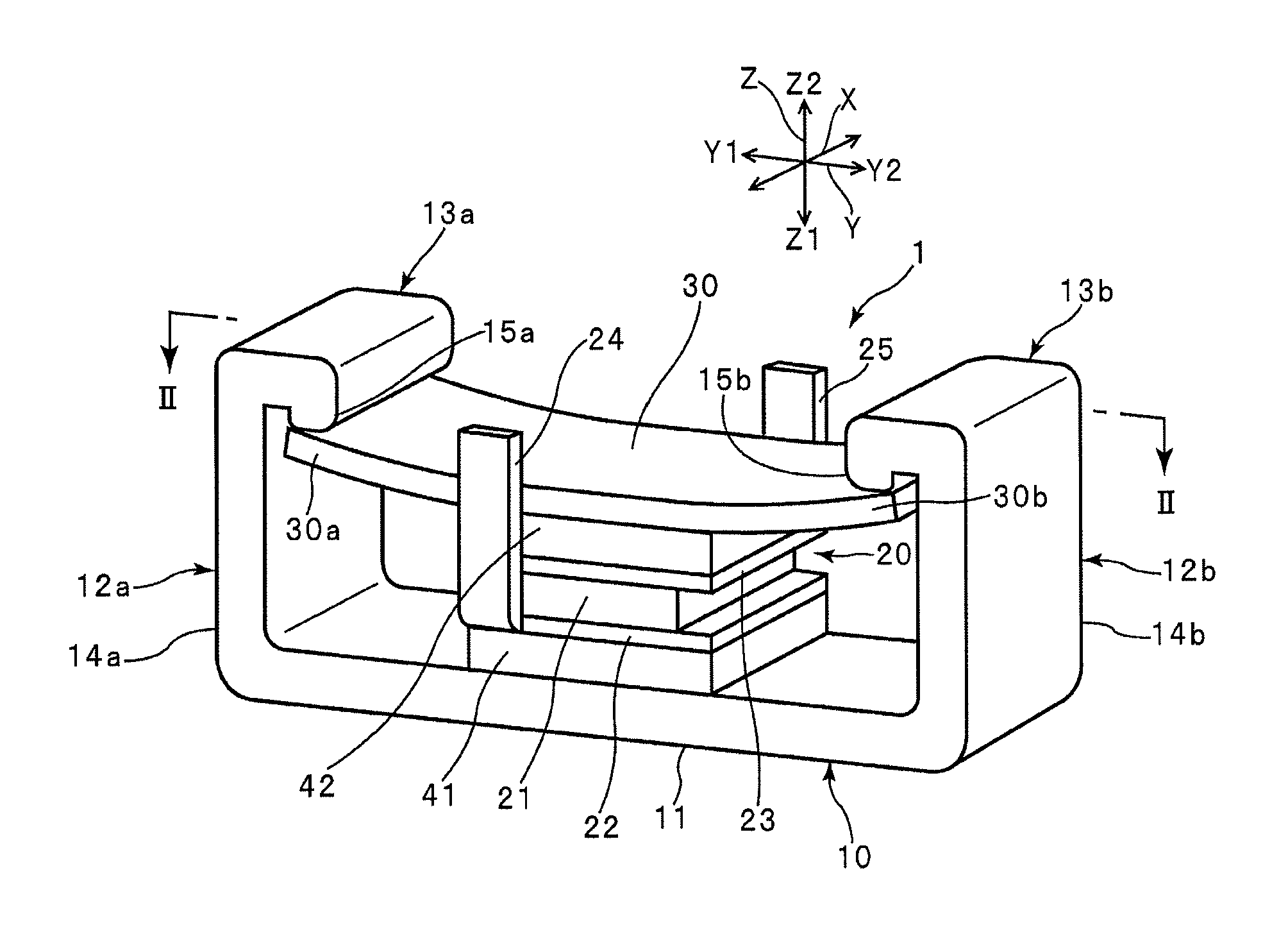
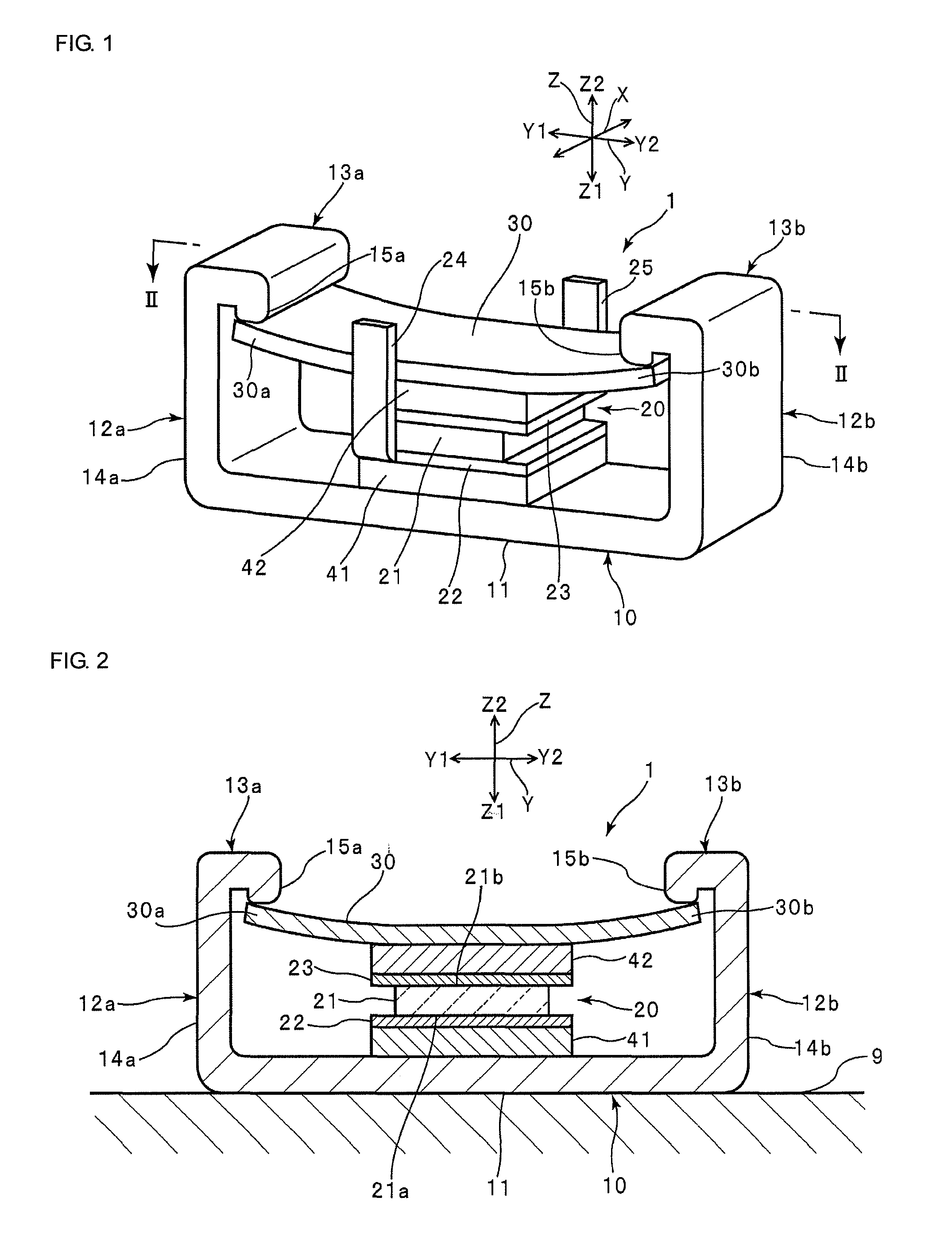
[0032]In this embodiment, a description will be given of an example of a piezoelectric power generator which is suitable for use in cases in which the magnitude of an external stress exerted on the piezoelectric power generator changes only in a predetermined direction (the longitudinal direction Y in FIG. 1). Specifically, for example, the piezoelectric power generator according to this embodiment is used as the power supply of a pneumatic pressure sensor for a tire, or the like, with its surface on the Z1 side of a base portion 11 described later mounted to the inner surface of the tire.

[0033]FIG. 1 is a schematic perspective view of a piezoelectric power generator according to a first embodiment as seen diagonally from the side. FIG. 2 is a schematic sectional view of the piezoelectric power generator taken along the sectioning line II-II shown in FIG. 1. As shown in FIGS. 1 and 2, a piezoelectric power generator 1 includes a support body 10, a piezoelectric element 20, a plate s...

second embodiment

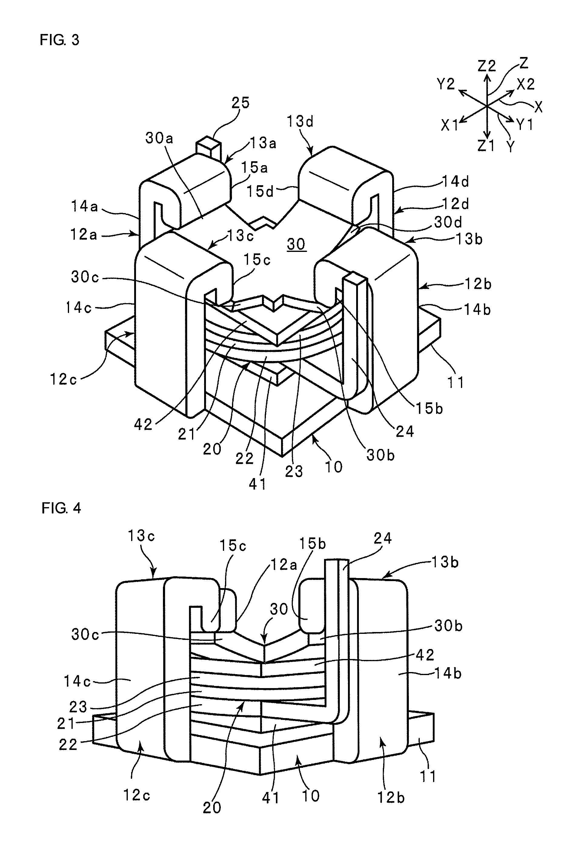
[0057]In this embodiment, a description will be given of an example of a piezoelectric power generator which is suitable for use in cases in which the magnitude of an external stress applied to the piezoelectric power generator changes in both the longitudinal direction Y and the width direction X. Specifically, the piezoelectric power generator according to this embodiment is used as, for example, a mobile phone's backup power supply used together with a main power supply such as a lithium battery, with its surface on the Z1 side of the base portion 11 described later mounted to the heel portion, toe portion, or the like of a shoe sole.

[0058]FIG. 3 is a schematic perspective view of a piezoelectric power generator according to a second embodiment as seen diagonally from the side. FIG. 4 is a schematic side view of the piezoelectric power generator according to the second embodiment. In this embodiment, the plate spring 30 is supported on the support body 10 at both of its both ends...

third embodiment

[0062]FIG. 5 is a schematic perspective view of a piezoelectric power generator according to a third embodiment as seen diagonally from the side. FIG. 6 is a schematic sectional view of the piezoelectric power generator taken along the sectioning line VI-VI shown in FIG. 5.

[0063]The configuration of the piezoelectric power generator according to this embodiment is the same as that of the piezoelectric power generator according to the first embodiment mentioned above, except for the configuration of the support body. In the piezoelectric power generator according to this embodiment, the support body 10 includes a plurality of pairs of leg portions 16a and 16b, in addition to the base portion 11 and the first and second claw portions 12a and 12b. Specifically, as shown in FIG. 5, the plurality of pairs of leg portions 16a and 16b extend to the side Z1 opposite to the piezoelectric element 20 from each of both ends of the base portion 11 along the width direction X. The leg portions 16...


PUM


Abstract

A piezoelectric power generator that includes a support body, a piezoelectric element, and a bias compressive stress applying member. The piezoelectric element is placed on the support body. The piezoelectric element has a piezoelectric plate that is polarized in the thickness direction, and first and second electrodes that are each provided on a surface of the piezoelectric plate. The bias compressive stress applying member is supported on the side above the piezoelectric element by the support body. The bias compressive stress applying member applies to the piezoelectric element a bias compressive stress acting in the thickness direction of the piezoelectric plate, so that the magnitude of a compressive stress in the piezoelectric plate changes with a change in externally applied stress.

Description

CROSS REFERENCE TO RELATED APPLICATIONS[0001]The present application is a continuation of International Application No. PCT / JP2009 / 004383, filed Sep. 4, 2009, which claims priority to Japanese Patent Application No. JP2008-231091, filed Sep. 9, 2008, the entire contents of each of these applications being incorporated herein by reference in their entirety.FIELD OF THE INVENTION[0002]The present invention relates to a piezoelectric power generator, and more specifically to a piezoelectric power generator which is mounted to, for example, an automobile or the tires of an automobile, vibrates upon application of acceleration or distortion, and generates electric power due to the piezoelectric effect.BACKGROUND OF THE INVENTION[0003]In the related art, piezoelectric power generators are known which vibrate upon application of acceleration, distortion, or the like, and generate electric power due to the piezoelectric effect. Using these piezoelectric power generators as power supplies el...

Claims


Application Information

Patent Timeline
Patent Type & Authority Patents(United States)
IPC IPC(8): H01L41/08
CPCH01L41/113H02N2/186H10N30/30
Inventor FUJIMOTO, KATSUMI
Owner MURATA MFG CO LTD
Why Eureka
Try Eureka