
Sliding type mobile terminal

a mobile terminal and sliding technology, applied in the direction of substation equipment, electrical equipment, telephone set construction, etc., can solve the problems of poor balance, rickety growth, and extremely difficult input operation, and achieve the effect of comfortable tv viewing and good operability

Inactive Publication Date: 2011-09-06
SHARP KK
View PDF22 Cites 9 Cited by
  • Summary
  • Abstract
  • Description
  • Claims
  • Application Information

AI Technical Summary

Benefits of technology

The present invention provides a sliding type mobile terminal that can switch between a vertically long state and a horizontally long state while maintaining a compact overall design. The first housing is stably supported in the sliding movement and the switching operation between the two states is smooth. The slide mechanism is provided with a support mechanism that allows for sliding movement and switching between the two states. The cam mechanism guides the switching operation of the first housing and ensures stability and fine appearance. The entire sliding type mobile terminal becomes compact.

Problems solved by technology

However, the terminal disclosed in the Japanese Unexamined Patent Application Publication No. 2006-115109 has only simple operating keys provided on the cover.
In addition, because the operating key arrangement differs from the usual arrangement, there was a problem that made an input operation extremely difficult.
However, in the mobile phone of Japanese Unexamined Patent Application Publication No. 2003-338866, the pin which is a pivot of sliding movement and rotation of the display pail is positioned at the upper end of the body, and there is only one pin for the display part to slide and rotate by being held by a single hand, causing a poor balance and thus creating a problem of growing ricketiness over years.
Further, since the pin is located at the upper end of the body, when the display part is placed in the horizontally long state, the upper end of the display part is placed further above the upper end of the body, causing a problem of poor stability when the body is placed on the desk.
Conversely, when the pin is positioned lower from the upper end of the body downward to increase a sense of stability, the region for the operating part has to be made smaller, so that ideal button arrangements could not be hoped for, resulting in poor operability.
To prevent this would necessitate enlarging the exterior shape of the product, then giving rise to a problem of worsening portability.

Method used


Image

  • Sliding type mobile terminal
  • Sliding type mobile terminal
  • Sliding type mobile terminal

Examples


Embodiment Construction

[0095]With reference to the drawings, the embodiments of the present invention will herein-after be described in detail.

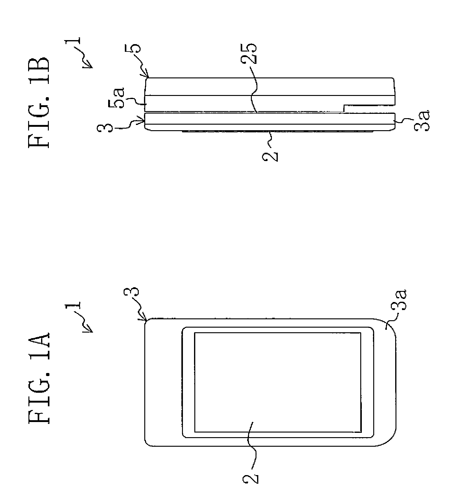
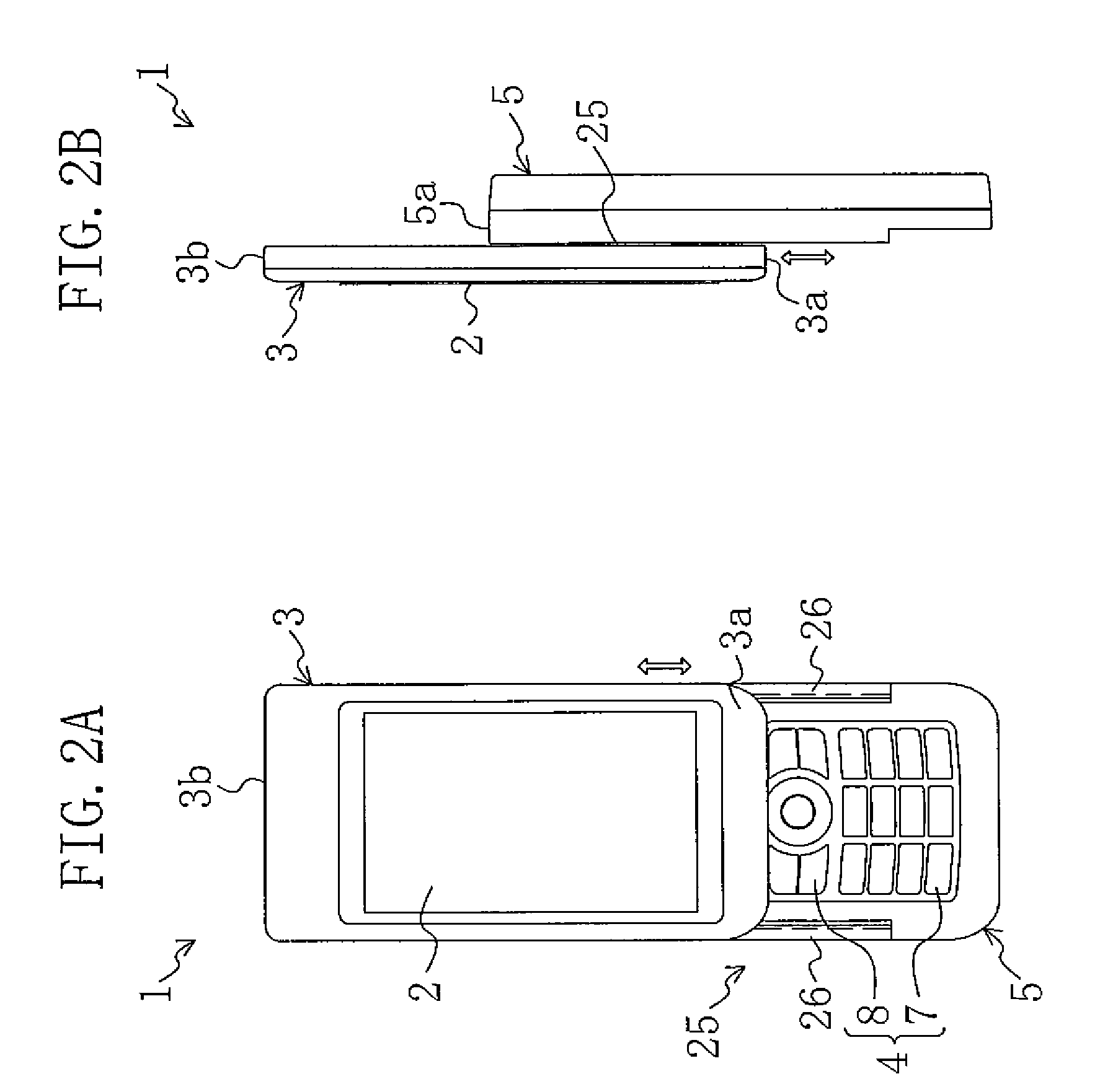
[0096]FIG. 1 shows a front view and a right side view of a sliding type mobile phone 1 as a sliding type mobile terminal according to an embodiment of the present invention in the state prior to sliding. FIG. 2 shows a front view and a right side view of a post-sliding state after a first housing 3 is slidably moved relative to a second housing 5. FIG. 3 shows a front view and a right side view of a state where the first housing 3, after the post-sliding state of FIG. 2, is in the process of switching from a vertically long state to a horizontally long state. FIG. 4 shows a front view and a right side view of a state where the first housing 3 is switched from the vertically long state to the horizontally long state.

[0097]The sliding type mobile phone 1 of the present embodiment is provided with the first housing 3 having on its surface a liquid crystal display part...


PUM


Abstract

A sliding mechanism is provided to couple slidably a first housing having on its surface a vertically long liquid crystal display part long in the vertical direction to a second housing having on its surface an operating part. This slide mechanism includes a rail part which is mounted on the surface of the second housing in a manner of extending in the vertical direction and is configured such that when the first housing has slidingly moved by means of the slide mechanism to the upper end side of the second housing, the operating part of the second housing will appear. Further, by means of the cam mechanism (support mechanism), the first housing is supported relative to the second housing in a switchable manner between the vertically long state and the horizontally long state.

Description

[0001]This non-provisional application claims priority based on Patent Application No. 2006-284825 filed in Japan on Oct. 19, 2006, the entire contents of which are hereby incorporated by reference.BACKGROUND OF THE INVENTION[0002]1. Field of the Invention[0003]The present invention relates to a sliding type mobile terminal such as mobile phones, mobile wireless communication equipment and the like, in which a first housing and a second housing are slidably coupled together.[0004]2. Description of the Related Art[0005]Recently, a one segment receiving service for mobile phones and mobile wireless communication equipment, which has captured attention as a service unique to terrestrial digital TV broadcasting, has started to be offered, and this service is commonly known as “One Seg”.[0006]“One Seg” is a service realized by Japan's exclusive broadcasting system that splits a 6-megahertz band for terrestrial digital TV broadcasting into 13 segments to be sent. The middle segment of the...

Claims


Application Information

Patent Timeline
Patent Type & Authority Patents(United States)
IPC IPC(8): H04M1/00F16C11/04H04M1/02H04M1/03
CPCH04M1/0233H04M1/0237H04B1/38
Inventor KUGA, AYAKOMATSUDA, KOHICHIIMAI, KIMIAKI
Owner SHARP KK
Learn More