Fuel injector nozzles, with labyrinth grooves, for gas turbine engines

a technology of fuel injector and nozzle, which is applied in the direction of machines/engines, mechanical equipment, lighting and heating apparatus, etc., can solve the problems of fuel accumulation carbon being formed in the air gap, and carbon not being as good an insulator as air

Active Publication Date: 2011-09-13
PARKER INTANGIBLES LLC
View PDF29 Cites 23 Cited by
  • Summary
  • Abstract
  • Description
  • Claims
  • Application Information

AI Technical Summary

Benefits of technology

[0007]As is preferred, the labyrinth seal is formed by labyrinth grooves in an unrestrained tip region of the nozzle to trap fuel (or other vapors depending on the application) as they enter and prevent fuel from moving further upstream into the insulating gap. In combination with the grooves, venting is added upstream to set up a favorable pressure differential to purge any fuel emanating from the grooves out of the fuel nozzle.

Problems solved by technology

This can result in carbon being formed in the air gap, which carbon is not as good an insulator as air.
In addition, the carbon may build up to a point where it blocks venting of the air gap to the air gap in the stem, which can lead to an accumulation of fuel in the air gap.
This can lead to diminished nozzle service life.

Method used


Image

  • Fuel injector nozzles, with labyrinth grooves, for gas turbine engines
  • Fuel injector nozzles, with labyrinth grooves, for gas turbine engines
  • Fuel injector nozzles, with labyrinth grooves, for gas turbine engines

Examples


Embodiment Construction

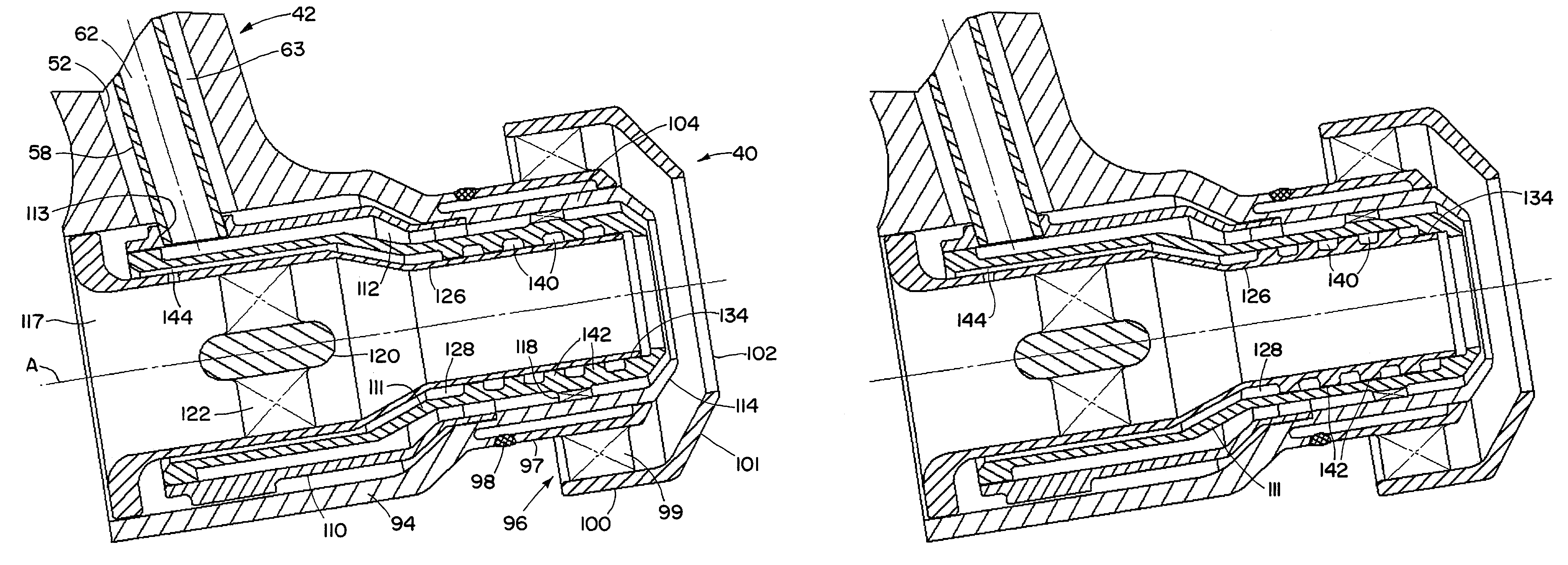
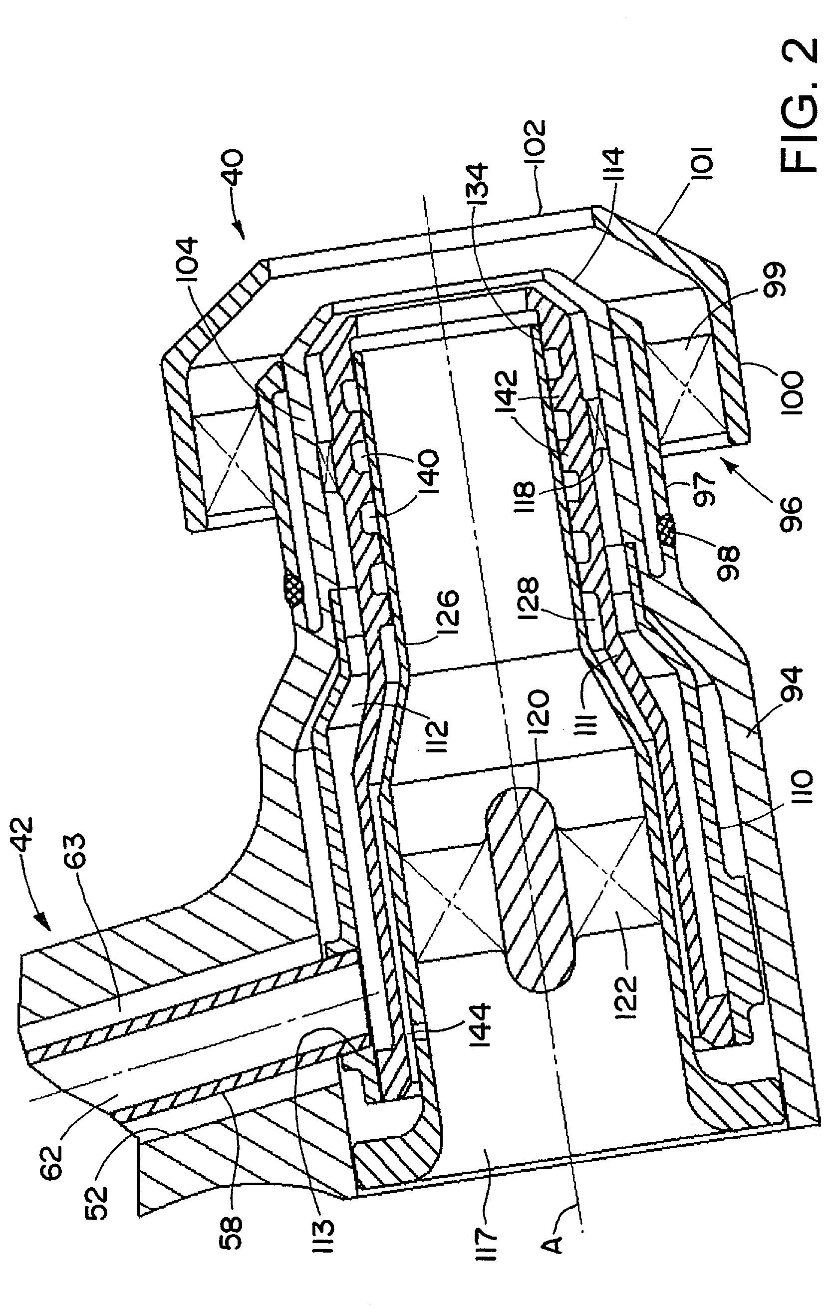
[0038]As above indicated, the principles of the present invention have particular application to fuel injectors and nozzles for gas turbine engines and thus will be described below chiefly in this context. It will of course be appreciated, and also understood, that the principles of the invention may be useful in other applications including, in particular, other fuel nozzle applications and more generally applications where a fluid is injected by a nozzle especially under high temperature conditions. In addition, an air blast type nozzle / injector is illustrated in the drawings, but the principles of the invention may be applied to other types of nozzles and injectors, such as pressure atomizer, multiple fuel circuit nozzles with one or more inlets or fuel conduits, etc. Such other nozzles / injectors may or may not have the illustrated central duct.

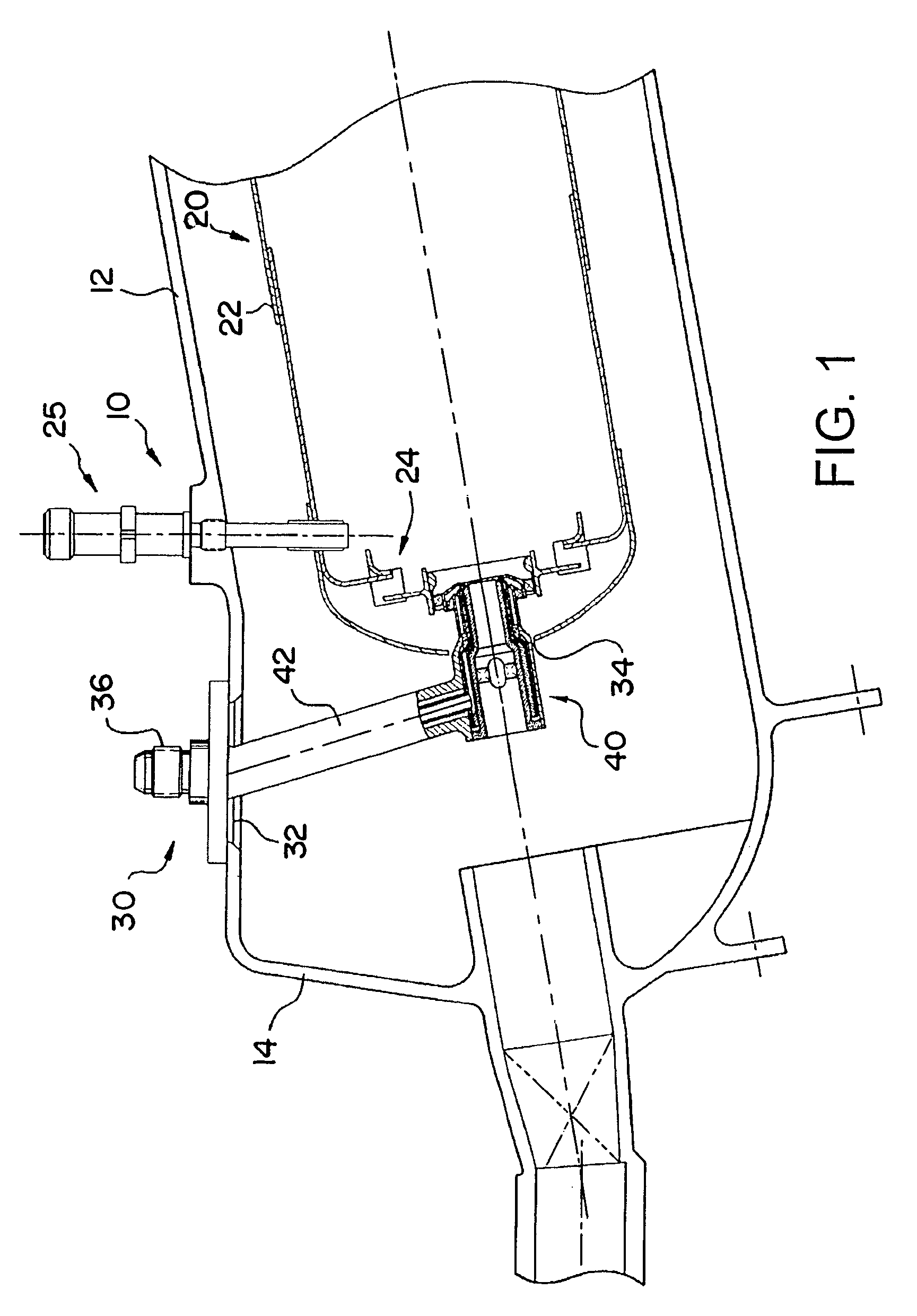
[0039]Referring now in detail to the drawings and initially to FIG. 1, a gas turbine engine for an aircraft is illustrated generally at 1...


PUM


Abstract

A fuel injector for a gas turbine engine of an aircraft, and more particularly a novel and unique heatshield structure for a fuel nozzle wherein a labyrinth seal is uniquely provided in the nozzle to isolate a portion of an insulating gap from an interface whereat fuel may enter the insulating gap, and the insulating gap is provided with a positive purge flow for forcing vapors out of the insulating gap.

Description

RELATED CASE[0001]This application claims the benefit of the filing date of U.S. Provisional Application No. 60 / 912,458 filed Apr. 18, 2007, which is hereby incorporated herein by reference.FIELD OF THE INVENTION[0002]The present invention relates generally to injectors and nozzles for high temperature applications, and more particularly to fuel injectors and nozzles for gas turbine engines of aircraft.BACKGROUND[0003]Fuel injectors for gas turbine engines on an aircraft direct fuel from a manifold to a combustion chamber of a combustor. The fuel injector typically has an inlet fitting connected to the manifold for receiving the fuel, a fuel nozzle located within the combustor for spraying fuel into the combustion chamber, and a housing stem extending between and fluidly interconnecting the inlet fitting and the fuel nozzle. The housing stem typically has a mounting flange for attachment to the casing of the combustor.[0004]Fuel injectors are usually heat-shielded because of a high ...

Claims


Application Information

Patent Timeline
Patent Type & Authority Patents(United States)
IPC IPC(8): F02C1/00F02G3/00
CPCF23R3/14F23R3/283Y02T50/675Y02T50/60
Inventor PELLETIER, ROBERT R.GUDIPATI, RAVICARREL, MICHAEL
Owner PARKER INTANGIBLES LLC
Why Eureka
Try Eureka