Vehicular door mirror device

a technology of mirror device and mirror, which is applied in the direction of mirrors, mountings, instruments, etc., can solve the problems of difficult to form a plurality of dimples on one of the opposing surfaces of the housing components, and the wall thickness is relatively large, so as to achieve easy visual observation, suppress wind roar, and the effect of not affecting appearan

Inactive Publication Date: 2011-09-13
HONDA LOCK MFG CO LTD
View PDF22 Cites 7 Cited by
  • Summary
  • Abstract
  • Description
  • Claims
  • Application Information

AI Technical Summary

Benefits of technology

[0008]With the first feature of the invention, even if the traveling wind flows inwards from between the opposed surfaces of the two housing components, an air flow is disturbed by the plurality of recesses in the collar provided in one of the housing components, and thus, a flow speed becomes lower, so that the generation of wind roar can be suppressed to the utmost.
[0009]With the second feature of the invention, the collar provided on one of the housing components is superposed on the other housing component from the inside. Therefore, the collar cannot be visually observed from the outside and thus, the appearance cannot be impaired. On the other hand, in a mirror device in which a dimple is formed in one of opposed surfaces of both housing components, the dimple is located at a flow inlet of traveling wind and easily visually observed from the outside, thereby bringing about the degradation of an appearance.
[0010]With the third feature of the invention, the collar guides the assembling of both housing components to facilitate the alignment of the housing components with each other, and thus, it is possible to enhance the assemblability.

Problems solved by technology

Thus, in order to form dimples, it is required that the wall thickness is relatively large, and it is difficult to form a plurality of dimples in one of the opposed surfaces of the housing components.

Method used


Image

  • Vehicular door mirror device
  • Vehicular door mirror device
  • Vehicular door mirror device

Examples


first embodiment

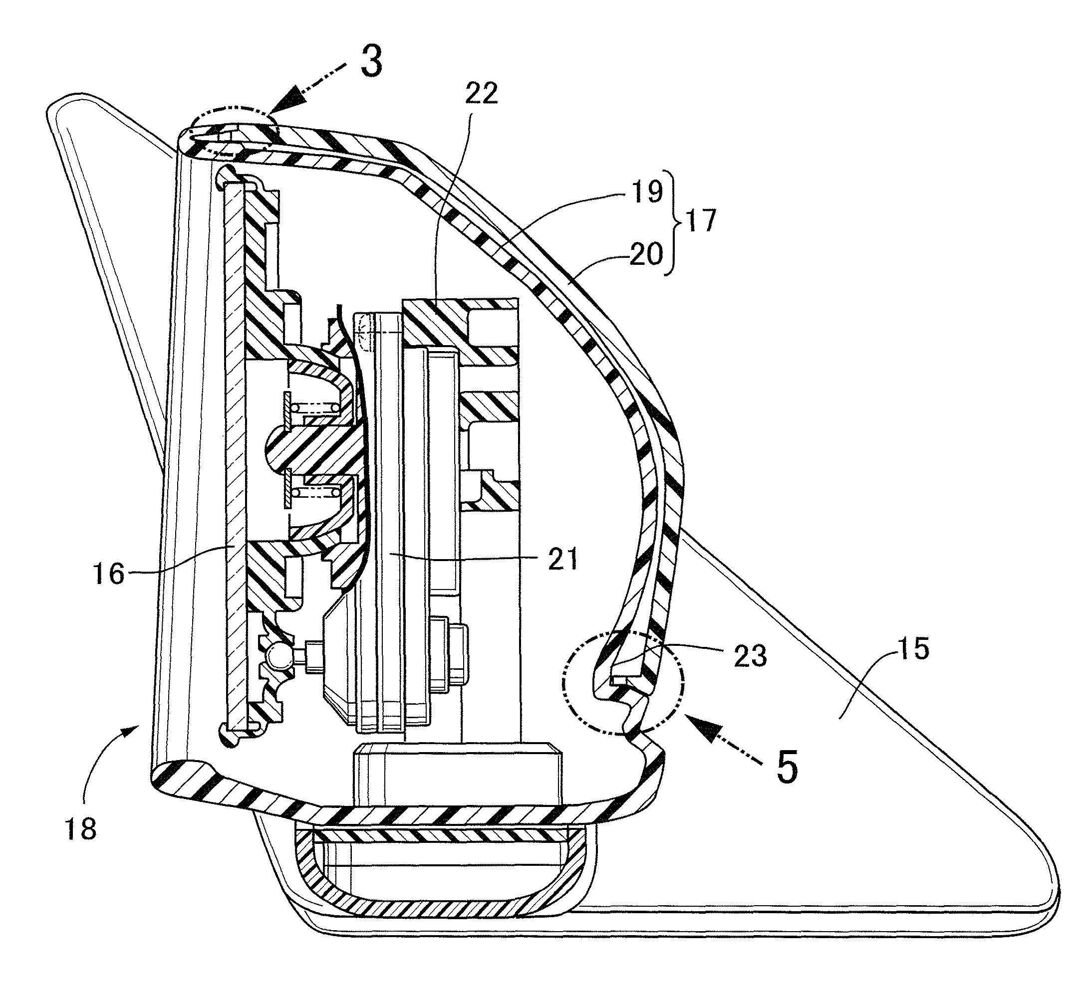
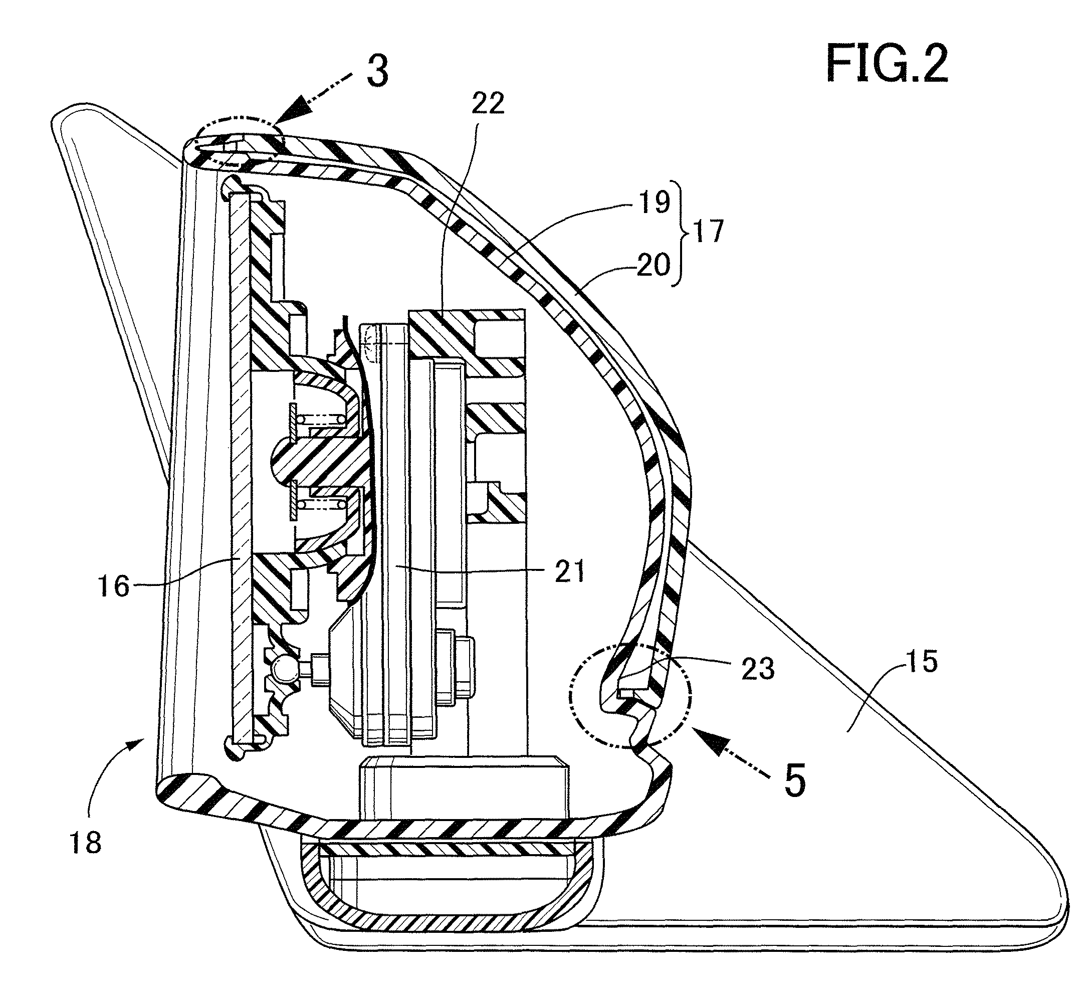
[0036] the collars 20a and 20b are integrally and projectingly provided on one of the housing body 19 and the decorative 20, i.e., on the decorative cover 20 to extend so that the collars 20a and 20b are superposed on the housing body 19 at the opposed sections of the housing body 19 and the decorative cover 20, and the pluralities of recesses 25 are provided in the juxtaposed manner at the tip ends of the collars 20a and 20b. Therefore, even if running wind enters inwards from between the opposed sections of the housing body 19 and the decorative cover 20, the air flow is disturbed by the pluralities of recesses 25 in the collars 20a and 20b provided in the decorative cover 20 and thus, it is possible to suppress the generation of a wind roar to the utmost.

[0037]A level of a sound pressure of the wind roar generated when the recesses 25 are provided in the juxtaposed manner at the tip ends of the collars 20a and 20b according to the present invention is shown by a broken line in FI...

second embodiment

[0040]FIGS. 8 to 11 show the present invention.

[0041]Referring to FIG. 8, a mirror device 27 having a housing 28 is turnably supported on a base 26 mounted on a side door of a vehicle (not shown). The housing 28 is comprised of two housing components: first and second housing halves 29 and 30 coupled to each other. The first housing half 29 is formed into a bowl-shape, and the second housing half 30 is formed into cylindrical shape in such a manner that it is connected to an opened end of the first housing half 29.

[0042]Lower portions of the first and second housing halves 29 and 30 form a tetragonal opening 31 as shown in FIG. 9, and a support shaft 32 for turnably supporting the mirror device 27 on the base 26 is disposed in the opening 31.

[0043]Referring to FIGS. 10 and 11, a collar 29a is integrally and projectingly provided on the entire periphery of the opened end of the first housing half 29 in an opposed relation to one end of the second housing half 30 from the inside, so t...

third embodiment

[0046]FIGS. 12 to 14 show the present invention.

[0047]It should be noted that the same reference numerals and characters are affixed to portions or components corresponding to those in the first embodiment, and the detailed description of them is omitted.

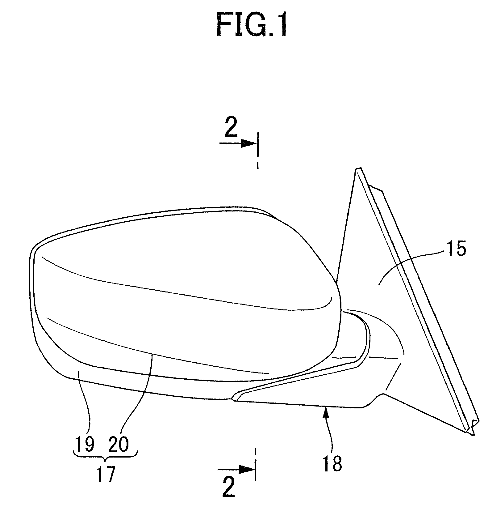
[0048]Referring to FIG. 12, a mirror device 36 is turnably supported on a base 35 mounted on a side door of a vehicle (not shown), and has a housing 37 adapted to cover a mirror 16 from the front during traveling of the vehicle. The housing 37 is comprised of two housing components; a housing body 38 and a visor 39 coupled to each other.

[0049]The housing body 38 is formed into a bowl-shape in such a manner that the mirror 16 is disposed in an opening, so that the housing body 38 is opened rearwards during traveling the vehicle. The visor 39 is formed so that a portion thereof is folded back into the opening in the housing body 38 to cover the periphery of the mirror 16. The visor 39 is coupled to an opened edge of the housing body 3...


PUM


Abstract

A vehicular mirror device includes a housing which is comprised of two housing components at least partially opposed to each other, and which is adapted to cover a mirror from the front during traveling of a vehicle. A collar is integrally and projectingly provided on one of the housing components to extend so that it is superposed onto the other housing component at opposed portions of both the housing components, and a plurality of recesses are provided in a juxtaposed manner in a tip end of the collar. This suppresses to the utmost the generation of a wind roar due to traveling wind flowing into between opposed portions of the housing components.

Description

BACKGROUND OF THE INVENTION[0001]The present invention relates to a vehicular mirror device comprising a housing which is comprised of two housing components at least partially opposed to each other, and which is adapted to cover a mirror from the front during traveling of a vehicle.DESCRIPTION OF THE RELATED ART[0002]If gaps are created at small and constant distances between a plurality of members constituting a vehicular mirror device, a wind roar is generated by flowing of traveling wind entering the gaps at a constant flow speed. There is a vehicular mirror device already known from Japanese Patent Application Laid-open No. 11-78695, in which a plurality of dimples are formed at least one of opposed surfaces of a mirror base and a housing in order to reduce such a wind roar.[0003]When the housing comprises two housing components, however, it is common that if dimples are formed in one of opposed surfaces of the housing components by applying the technique disclosed in the above...

Claims


Application Information

Patent Timeline
Patent Type & Authority Patents(United States)
IPC IPC(8): G02B7/182B60R1/06
CPCB60R1/06
Inventor WAKABAYASHI, SHINICHI
Owner HONDA LOCK MFG CO LTD
Why Eureka
Try Eureka