Optical ferrule

a technology of optical fibers and ferrules, applied in the field of optical ferrules, can solve the problems of significant loss of multimode optical fibers at connection points, and achieve the effects of less cost, reduced cost, and reduced cos

Active Publication Date: 2011-09-13
FUJIKURA LTD
View PDF5 Cites 16 Cited by
  • Summary
  • Abstract
  • Description
  • Claims
  • Application Information

AI Technical Summary

Benefits of technology

[0010]Meanwhile, a demand to use the multimode optical fibers for long-distance communication with several hundreds of meters has been increased. The multimode optical fibers are less expensive than single optical fibers. Thus, it is possible to create a network at low cost. However, on the other hand, connection loss of the multimode optical fibers at connection points is considerable since a damping rate of the multimode optical fibers is higher than the single optical fibers. Recently, optical fibers are often used in circumstances with a lot of foreign materials. Therefore, it is necessary to reduce connection loss due to the foreign materials.
[0011]The present invention has been made in consideration for the above-mentioned problem. It is an object of the present invention to provide an optical ferrule capable of controlling an increase of connection loss due to foreign materials between connection end faces, and capable of maintaining a good PC connection.
[0013]According to the optical ferrule described above, the rest of foreign materials after cleaning when a connection process are deposited in the grooves, and therefore, the deposited foreign materials are prevented from entering spaces between each connection end face during a butt-connection. In addition, even if the optical ferrule gathers up the foreign materials on inner walls of the optical adapter during the butt-connection, the foreign materials are collected in the collecting portion. Thus, the increase of connection loss due to the foreign materials can be avoided.

Problems solved by technology

However, on the other hand, connection loss of the multimode optical fibers at connection points is considerable since a damping rate of the multimode optical fibers is higher than the single optical fibers.

Method used


Image

  • Optical ferrule
  • Optical ferrule
  • Optical ferrule

Examples


Embodiment Construction

[0021]Hereinafter, description will be made below in detail of an embodiment of the present invention.

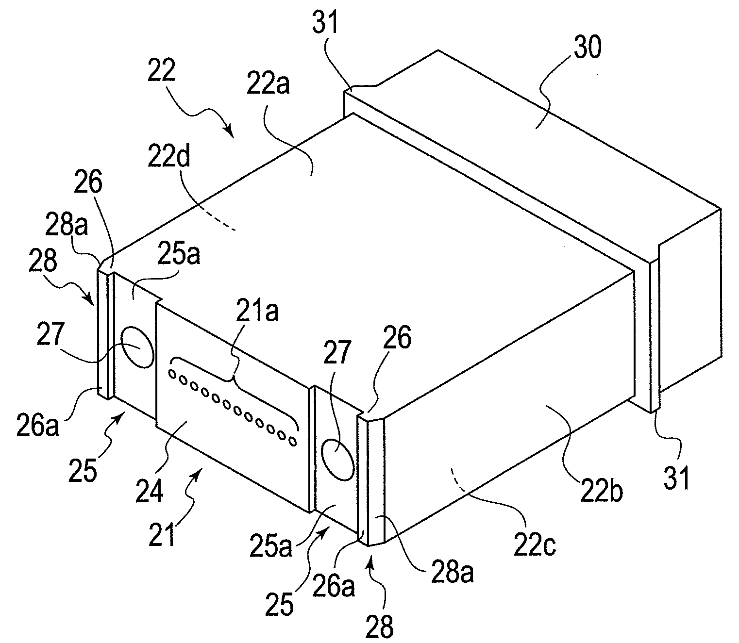
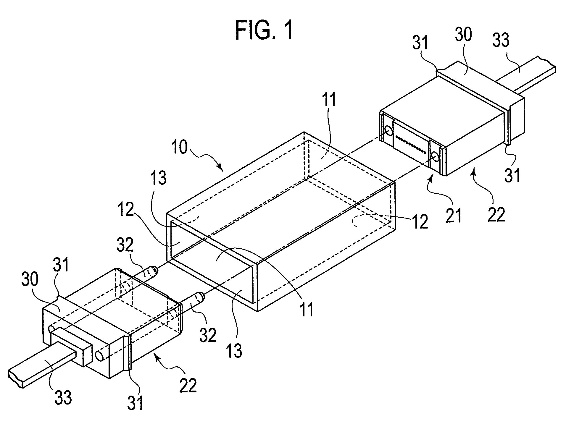
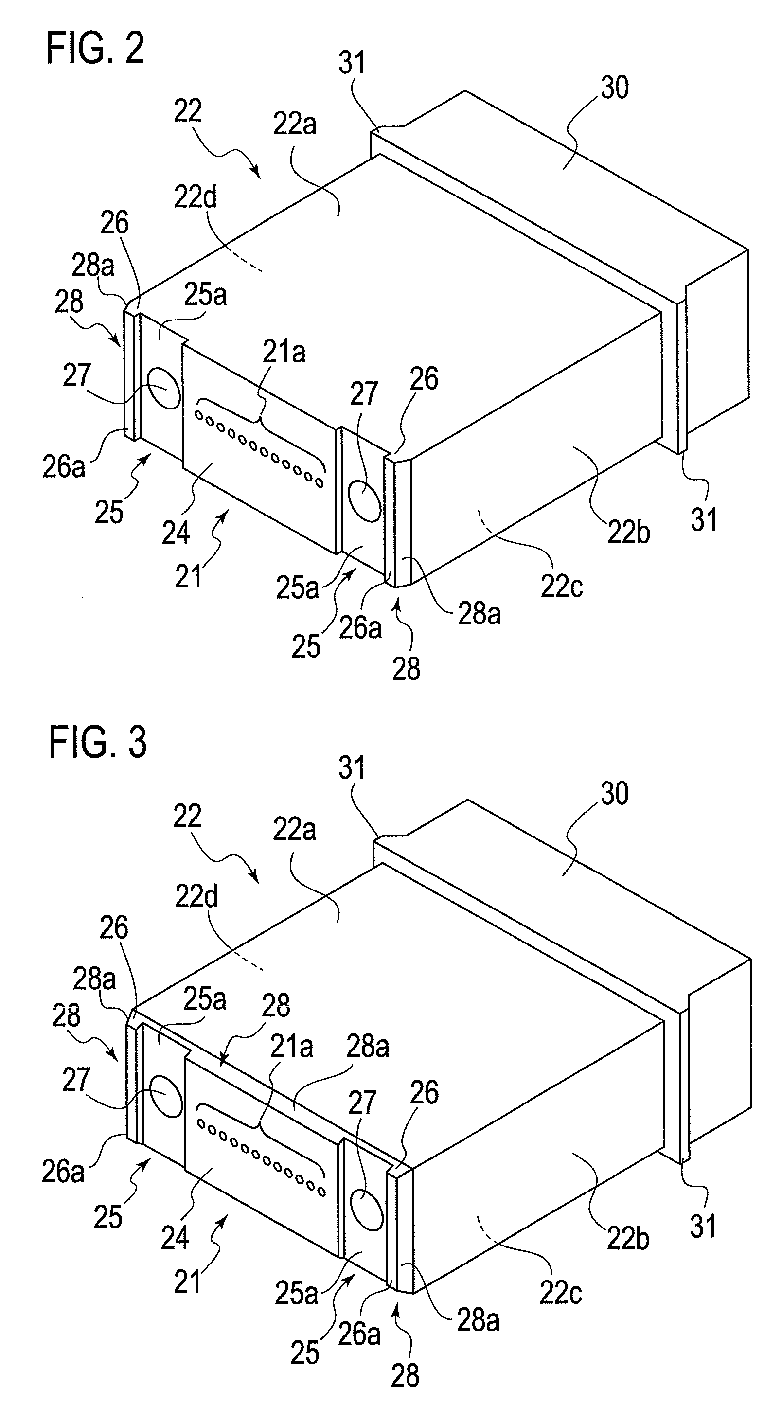
[0022]An optical ferrule according to the present embodiment is an MT ferrule standardized according to JISC 5981, IEC 61754-5 and the like. As similar to a conventional MT ferrule, the optical ferrule according to the present embodiment is positioned by guide pins. Then, respective optical fibers in a corresponding MT ferrule are connected by means of a PC connection.

[0023]Note that, in the following description, directions or locations are defined as follows. A side provided with a connection end face 21 of a ferrule body 22 is defined as a “front” side, and a side located on the opposite side of the connection end face 21 is defined as a “rear” side. The connection end face 21 has a plurality of optical fiber insertion holes 21a arranged in at least one line. Thus, a direction along the line is defined as a “right” or “left” direction, and a direction perpendicular to the line is...


PUM


Abstract

An optical ferrule butt-connected in an optical adapter, includes: a ferrule main body; a connection end face in a front surface of the main body; a pair of grooves on the connection end face of the main body; guide pin insertion holes in bottom surfaces of the respective grooves; optical fiber insertion holes in the connection end face, the holes being arranged in a line; and foreign material collecting portions at least at a pair of corresponding sides of the connection end face. The groove has a width larger than a diameter of the guide pin insertion hole. The foreign material collecting portions respectively have a wall for connecting the connection end face with a side surface of the ferrule main body to form a space for collecting a foreign material with an opposite connection end face of a corresponding optical ferrule and an inner wall of the optical adapter.

Description

BACKGROUND OF THE INVENTION[0001]1. Field of the Invention[0002]The present invention relates to an optical ferrule. Specifically, the present invention relates to an optical ferrule that is butt-connected in an optical adapter by being guided by guide pins.[0003]2. Description of the Related Art[0004]In general, an optical ferrule (optical connector), which is standardized according to JIS C 5981, IEC 61754-5 and the like, is called an MT (Mechanically Transferable) ferrule (MT connector). The MT ferrule is used for connecting one or more optical, and has a positioning mechanism by use of guide pins for a high-accuracy positioning of each optical fiber.[0005]The MT ferrule is provided with a pair of guide pin insertion holes on an end surface thereof to insert the guide pins for positioning the optical ferrule, and also provided with optical fiber insertion holes to insert the respective optical fibers between the guide pins. The optical fiber insertion holes are aligned in the sam...

Claims


Application Information

Patent Timeline
Patent Type & Authority Patents(United States)
IPC IPC(8): G02B6/38
CPCG02B6/3882G02B6/3885
Inventor TAKAOKA, ATSUSHINISHIMURA, AKITOHAYASHI, YUKIO
Owner FUJIKURA LTD
Why Eureka
Try Eureka