
Drive train of a motor vehicle

a technology of a drive train and a motor vehicle, which is applied in the direction of alternative steering control, machines/engines, braking systems, etc., can solve the problems of inability to actuate the braking action of the combustion engine, during the thrust operation of the vehicle, and achieve the effect of increasing the complexity of the cos

Inactive Publication Date: 2011-09-13
ZF FRIEDRICHSHAFEN AG
View PDF23 Cites 2 Cited by
  • Summary
  • Abstract
  • Description
  • Claims
  • Application Information

AI Technical Summary

Benefits of technology

Enables efficient and transparent activation and termination of the coasting mode, reducing fuel consumption and noise while maintaining braking control, without increasing system complexity or cost.

Problems solved by technology

In both these operating modes, however, the braking action of the combustion engine, during thrust operation of the vehicle, is not available.

Method used


Image

  • Drive train of a motor vehicle
  • Drive train of a motor vehicle

Examples


Embodiment Construction

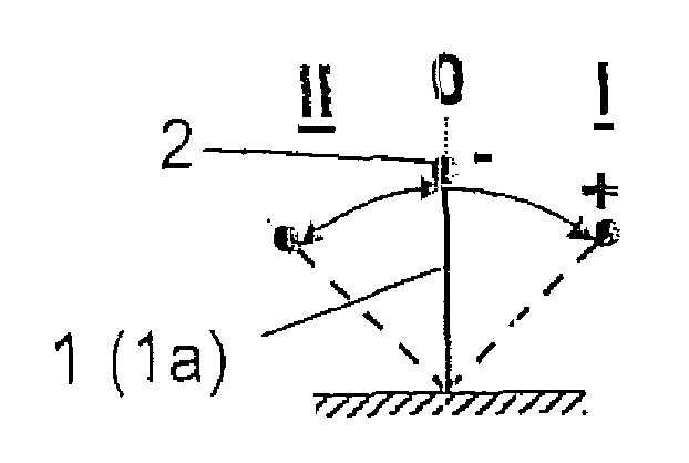
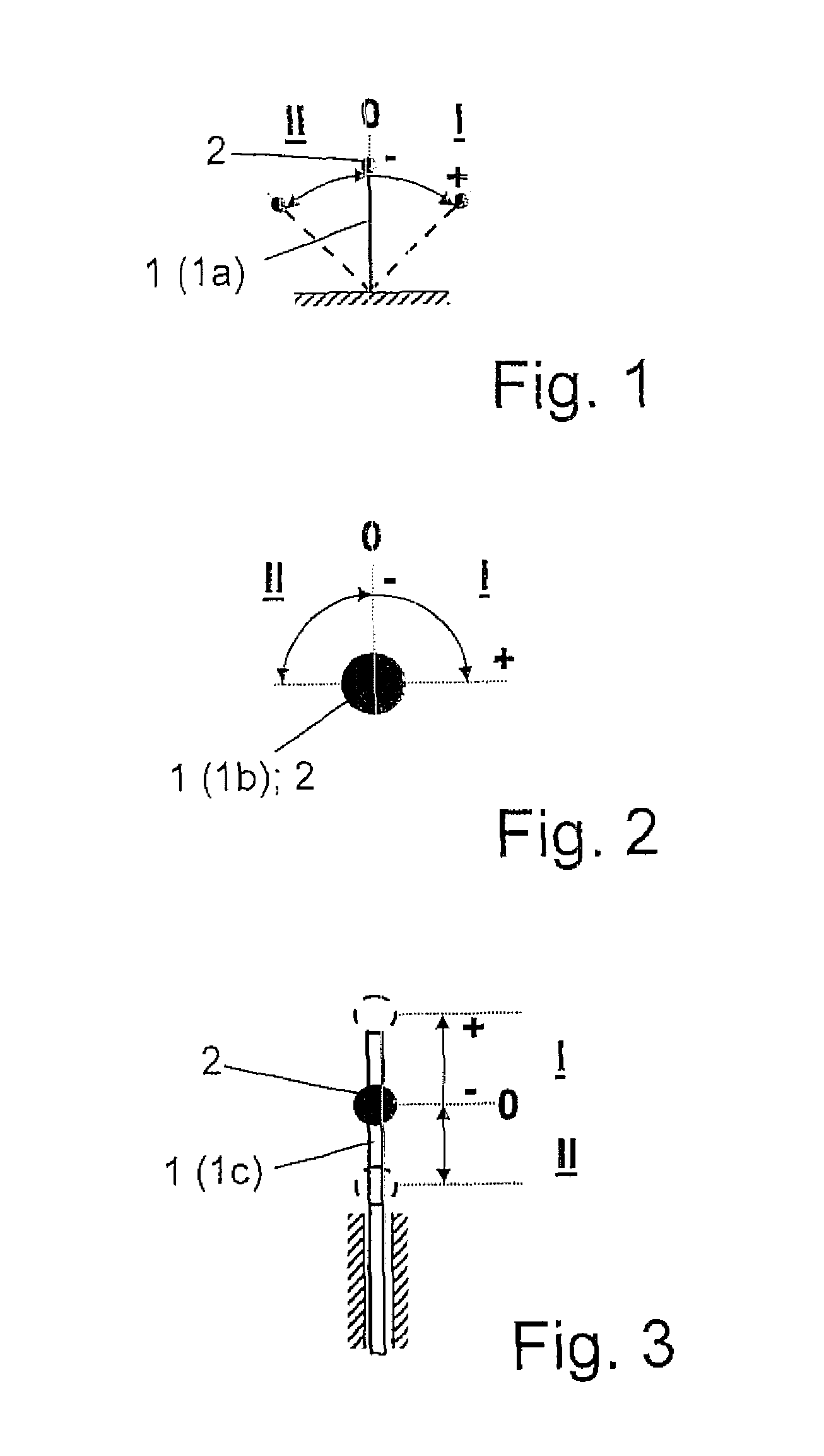
[0030]According to FIG. 1, a preselector element 1 of the additional brake (not shown here) arranged in a drive train of the motor vehicle, known in itself (not illustrated further), is made as a pivoting lever 1a with a knob 2. In its starting position, the pivoting lever 1a is at a zero or a rest position designated by “0” and it can be swivelled in two different actuation directions “I” and “II”.

[0031]As can be seen in this case, the two actuation directions “I” and “II” are preferably exactly opposite one another. However, other actuation directions “I” and “II”, different from one another, are also possible (not illustrated further) and are thus covered by the invention.

[0032]According to this example embodiment, the actuation direction “I” is associated with the selection of a defined braking resistance to be applied by the additional brake, such that as the swivel angle of the pivoting lever 1a is increased, the braking resistance increases.

[0033]In contrast, the actuation di...


PUM


Abstract

A drive train of a motor vehicle, with a drive engine, a torque converter, an additional brake, a retarder, a manual actuator device for a power control element, a manually operated preselector element for an operating range of the torque converter, a manually operated preselector element for selecting braking resistance of the additional brake, a manual control element for actuating a brake that decelerates the motor vehicle and an electronic control unit for exchanging and processing signals and data of the drive train and / or of the motor vehicle. The preselector element for the additional brake is connected to the electronic control unit such that starting from a zero position “0”, it can be actuated in a direction “I” for signaling the selection of a braking resistance of the additional brake, and also in another direction “II” for signaling the activation of a drive-power-off rolling or coasting operation mode.

Description

[0001]This application is a national stage completion of PCT / EP2006 / 012268 filed Dec. 20, 2006, which claims priority from German Application Serial No. 10 2006 004 080.5 filed Jan. 28, 2006.FIELD OF THE INVENTION[0002]The invention concerns a drive train of a motor vehicle.BACKGROUND OF THE INVENTION[0003]For a long time vehicles have been known which are equipped with a coasting function in order to reduce fuel consumption. This operates in such manner that when the driver throttles down, the driving internal combustion engine is disconnected from the driven vehicle wheels by disengaging a clutch in the drive train. The speed of the combustion engine can then be reduced to an idling speed so that fuel is saved. To reduce the consumption still more, it is also known, in such thrust operation phases of the motor vehicle with the drive power disconnected, to cut off the supply of fuel to the combustion engine completely although, in such a case, more effort is needed for the operatio...

Claims


Application Information

Patent Timeline
Patent Type & Authority Patents(United States)
IPC IPC(8): B60W10/04B60K20/00B60W10/00B60K26/00
CPCB60T10/00B60T10/02B60T13/585Y10T477/644Y10T74/2014Y10T477/82B60T17/00B60T7/08
Inventor GRIESMEIER, UWEREITZ, PETER
Owner ZF FRIEDRICHSHAFEN AG
Learn More