Puncturable catheter

a catheter and stent technology, applied in the field of catheters, can solve the problems of less tear resistan

Inactive Publication Date: 2011-09-13
WL GORE & ASSOC INC
View PDF89 Cites 89 Cited by
  • Summary
  • Abstract
  • Description
  • Claims
  • Application Information

AI Technical Summary

Benefits of technology

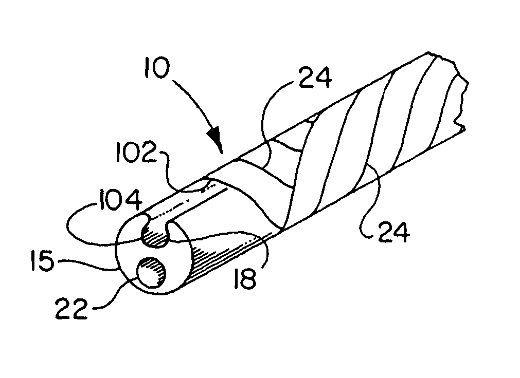
[0011]In a preferred embodiment, the thin covering is made from a thin tape of porous expanded polytetrafluoroethylene (ePTFE) helically wrapped about the exterior of a catheter shaft. Most preferably, the wrapping is accomplished in two opposing directions parallel to the length of the catheter shaft, resulting in a bias-ply construction. This thin covering offers good transparency and is easily punctured by the end of a guidewire, and yet is resistant to tearing at the puncture site.
[0012]Other materials may be used for the puncturable thin covering, including polyethylene terephthalate (PET). These materials may also offer good translucency, but may be less tear resistant than the helically wrapped ePTFE thin coverings.
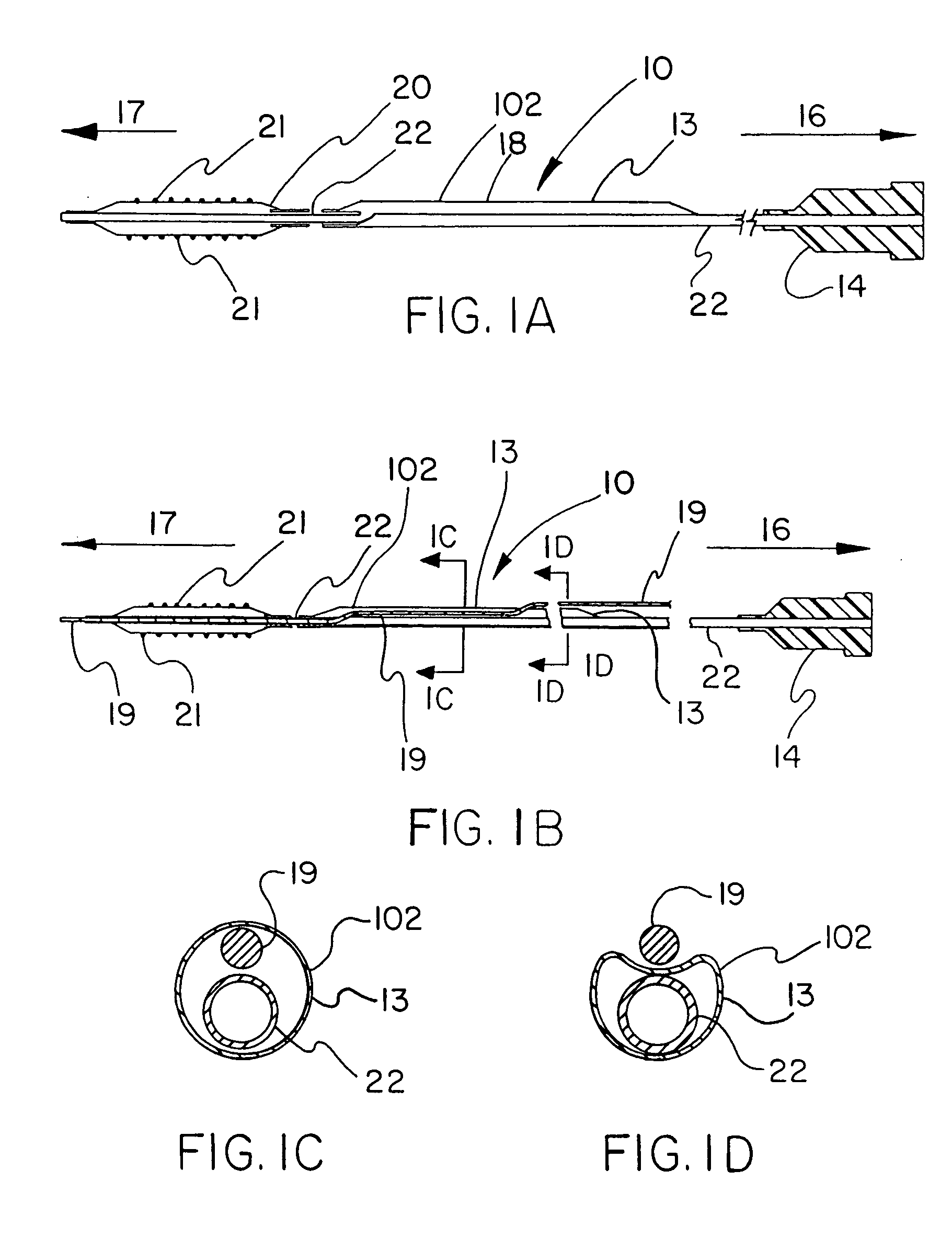
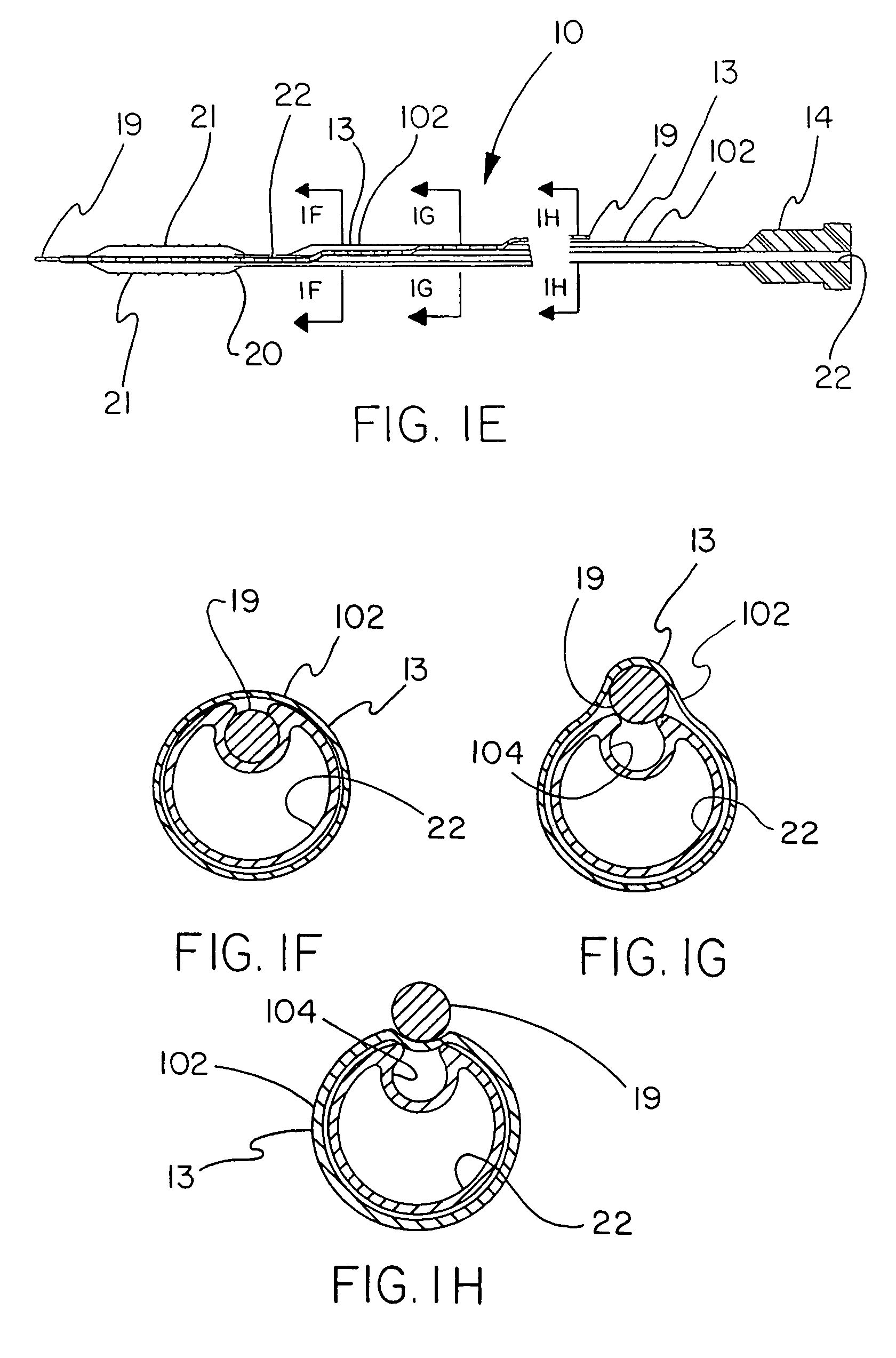
[0016]Other embodiments using the catheter shaft may be provided with a puncturable tubular form inserted into the slot. This tubular form may be made with filaments braided into the tubular form, or a tubular form made of helically wound filaments or from a thin polymeric material, with the tube having an inside diameter adequately large to accommodate a guidewire of the desired size. These tubes are fitted and secured into the slot formed into the catheter shaft, with the result that the outer surface of the braided or helically wound tube covers the exposed part of the slot and allows for the back end of a guidewire contained within the tube to be passed through any interstice between adjacent filaments of the braided or helically wound tube. When the tubular form is made from the thin polymeric material, the resulting tube inserted into the catheter shaft slot is puncturable at any desired location by the back end of a guidewire.
[0018]By adjustable length is meant that the length of the adjustable length guidewire catheter lumen may be changed by the application of easily applied manual axial force. In its axially extended or fully lengthened state, the adjustable length guidewire catheter lumen is at least 10% longer than when in the axially compressed, fully shortened state. More preferably, the adjustable length guidewire catheter lumen is adjustable by an amount of at least about 20%, or 30%, or 40%, or 50%, or 75%, or 100%, or 200%, or 400%, or 1000%, or 2000%.
[0019]The adjustable length guidewire catheter lumen is adjustable in length by virtue of being scrunchable. This means that this tubular component is easily shortened in length under axial force, without telescoping as by the successive sliding of overlapped concentric tubular sections. Various means of providing a scrunchable tube for use as the adjustable length guidewire catheter lumen include the provision of corrugations (i.e., wrinkles, or accordion pleats or folds), or by the use of a porous tube that compresses axially by reduction in total void space. These are further described below.
[0021]The ability of the catheter to be punctured by the back end of a guidewire at any desired location along the length of the puncturable section of the catheter allows the catheter assembly to be used effectively as desired in either OTW or RX mode.

Problems solved by technology

These materials may also offer good translucency, but may be less tear resistant than the helically wrapped ePTFE thin coverings.

Method used


Image

  • Puncturable catheter
  • Puncturable catheter
  • Puncturable catheter

Examples


Embodiment Construction

[0044]FIGS. 1A-1H describe the catheter 10 of the present invention provided with a thin, puncturable cover 102 over the guidewire lumen 18. Typically, catheter 10 may include devices such as a catheter balloon 20 and / or stent 21 at its distal end 17 and a hub 14 at the proximal end 16. As shown by FIGS. 1A-1H, the thin, puncturable cover 102, in this instance a thin-walled a thin tubular sheath 13 (forming guidewire lumen 18) designed to be punctured by the back end of a guidewire 19, may be placed coaxially about the inflation lumen 22. The length of the thin tubular sheath 13 may extend over all or part of the length of catheter shaft.

[0045]After feeding guidewire 19 through the distal section of the guidewire lumen 18 and into the thin-walled tubular sheath 13, the physician may chose any desired location along the length of thin-walled tubular sheath 13 at which to puncture the thin, puncturable cover 102 with the guidewire 19. In this fashion the physician may select his prefe...


PUM


Abstract

A catheter provided with a guidewire catheter lumen having a thin covering that is easily punctured by a guidewire at virtually any desired point along the catheter length. The thin covering may be integral with the catheter shaft, or may be a separate component that covers only the portion of the catheter shaft immediately adjacent the outer portion of the guidewire lumen, or may be a thin tubular construct that surrounds the entire catheter shaft. The covering is preferably relatively translucent, allowing for good visualization of the location of the end of the guidewire to enable puncturing of the covering at the desired location along the length of the catheter shaft. The covering is also preferably tear resistant at puncture sites. The catheter shaft is preferably made of a material having a color that provides good visibility against an operating field, and more preferably is phosphorescent either entirely or in part. Materials suitable for the catheter shaft are polymeric materials well known in the art; the catheter shaft may optionally be provided with metallic stiffening components such as wires or hypotubes along all or part of the catheter length.

Description

CROSS REFERENCE TO RELATED APPLICATIONS[0001]This application is a continuation-in-part of application Ser. No. 10 / 346,977 filed Jan. 17, 2003 now abandoned.FIELD OF THE INVENTION[0002]The present invention relates to the field of catheters for use with guidewires, and more particularly to such catheters intended for the delivery of a therapeutic agent or device.BACKGROUND OF THE INVENTION[0003]A variety of different therapies can be delivered within the human body by catheter devices. Therapeutic devices such as dilation balloons, stents, and embolic filters, and therapeutic agents such as drugs and radiation sources, may be positioned at or near the distal end of the catheter for delivery to a desired site within the body. The proximal end of the catheter is considered to be the end that remains outside of the body, manipulated by the medical practitioner.[0004]To aid in positioning of the distal end of the catheter within the body, typically the distal end of a guidewire is first...

Claims


Application Information

Patent Timeline
Patent Type & Authority Patents(United States)
IPC IPC(8): A61B1/12A61M29/00A61F2/958A61MA61M5/00A61M25/00A61M25/14
CPCA61M25/0043A61M25/005A61M25/10A61F2/958A61M25/0052A61M2025/1081A61M2025/0183A61M2025/0188A61M2025/1056
Inventor ARMSTRONG, JOSEPH R.CULLY, EDWARD H.FLURY, KEITH M.VONESH, MICHAEL J.
Owner WL GORE & ASSOC INC
Why Eureka
Try Eureka