Rack for analyzer and analyzer comprising such a rack

a rack and analyzer technology, applied in the field of racks, can solve the problems of increasing the complexity and the manufacturing cost of automatic clinical chemistry analyzers, and achieve the effect of low cos

Inactive Publication Date: 2011-09-13
ROCHE MOLECULAR SYST INC
View PDF5 Cites 27 Cited by
  • Summary
  • Abstract
  • Description
  • Claims
  • Application Information

AI Technical Summary

Problems solved by technology

A disadvantage of both approaches is that they increase the complexity and the manufacturing cost of automatic clinical chemistry analyzers.

Method used


Image

  • Rack for analyzer and analyzer comprising such a rack
  • Rack for analyzer and analyzer comprising such a rack
  • Rack for analyzer and analyzer comprising such a rack

Examples


example 1

Example of a Rack According to the Invention

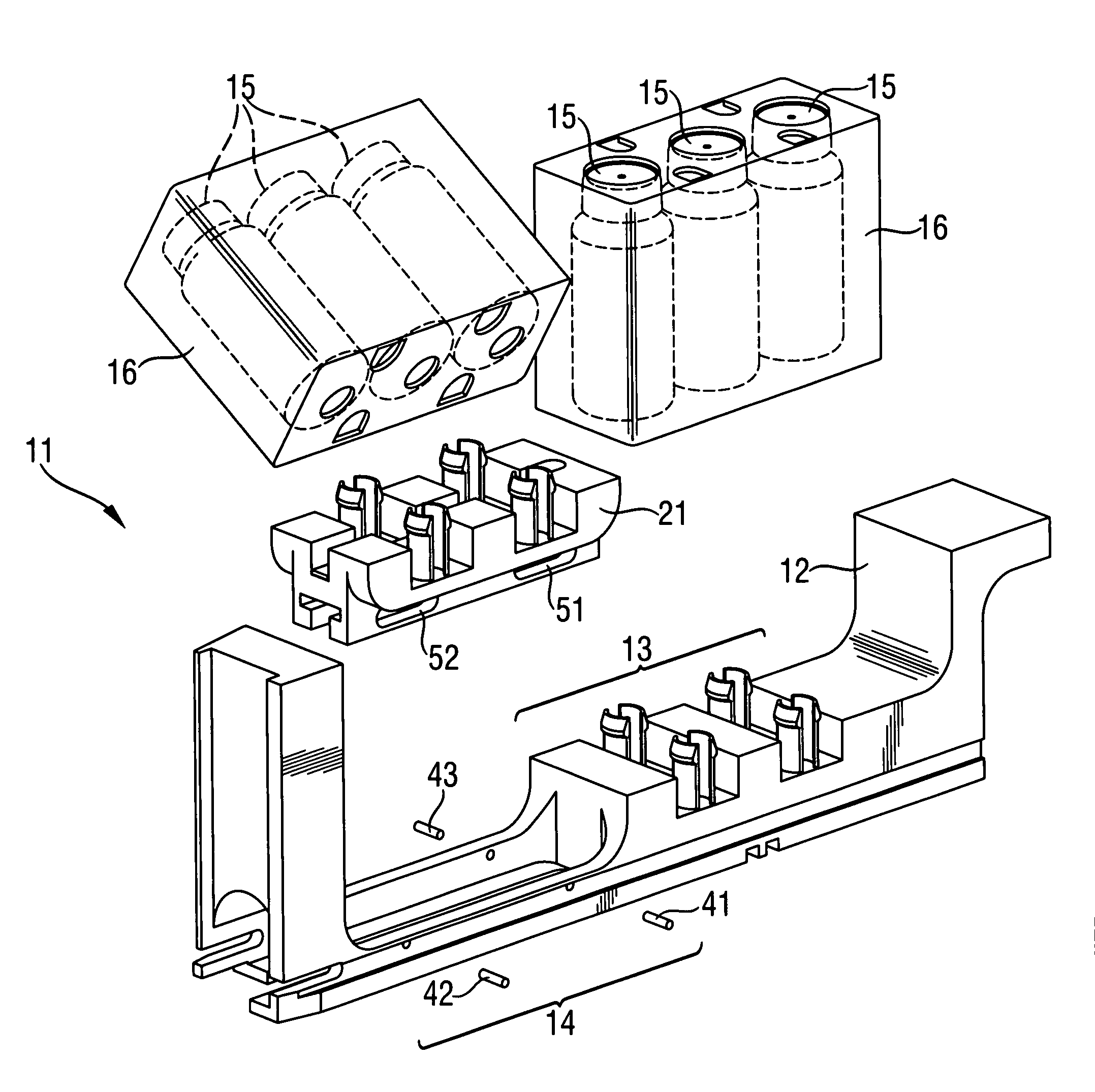
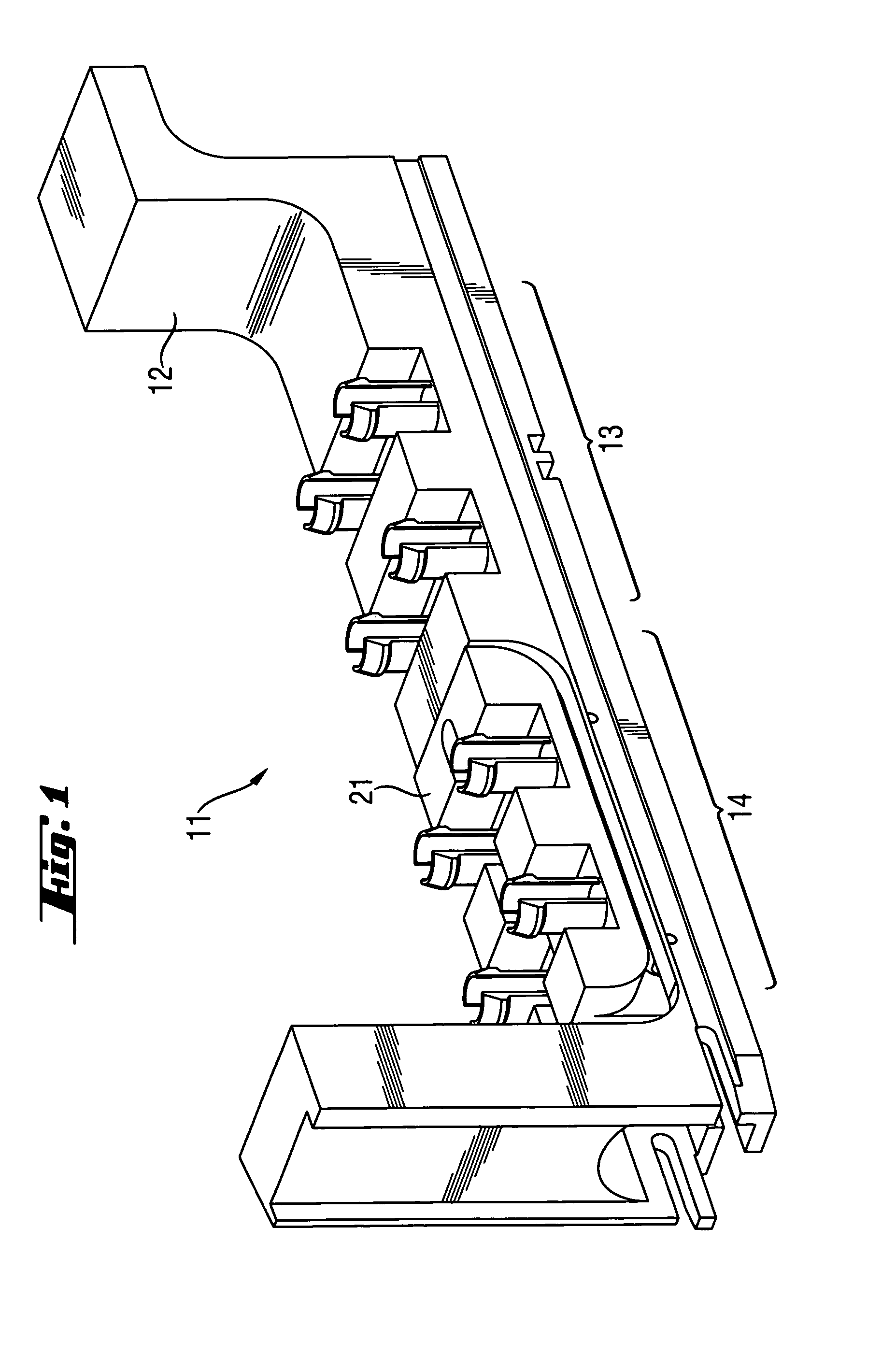
[0034]FIG. 1 shows a rack 11 according to the invention. Rack 11 has a frame 12 and a movable part 21. Frame 12 has at least one section 13 for holding a first liquid containing component (not shown) which does not have to be agitated and at least one section 14 for holding a second liquid containing component (not shown) which has to be agitated. The movable part 21 of the rack 11 is located in a section 14. The shape and size of section 14 allows movement of movable part 21 within predetermined limits.

[0035]Rack 11 may be made of any suitable material, such as, for instance a polycarbonate (PC).

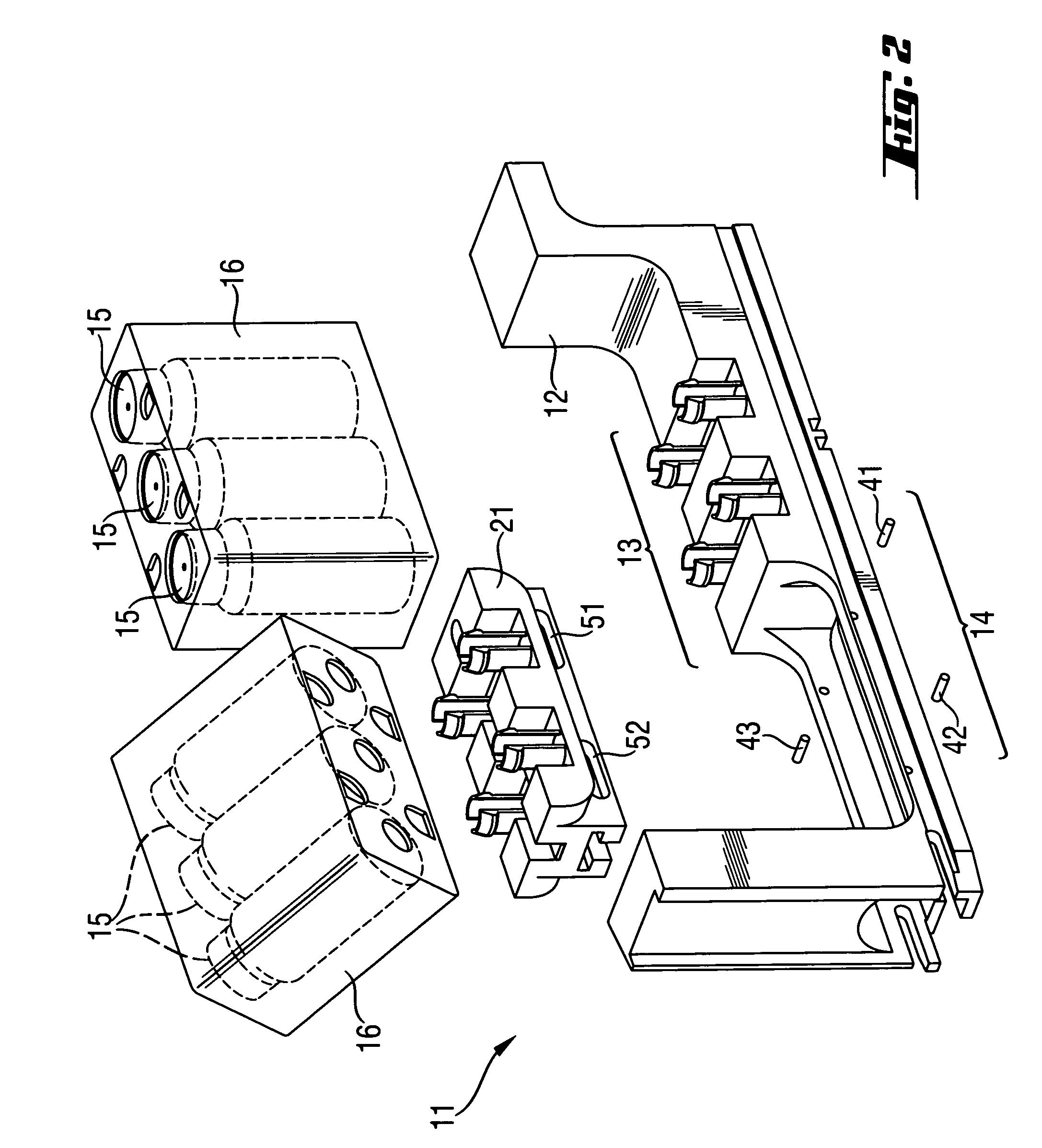
[0036]The first and the second liquid containing components may be a single liquid container or a component comprising a casing 16 which contains one or more liquid containers 15 (see FIG. 2). A component of the latter type is described in European Patent Application EP 0564970 A2.

[0037]FIG. 2 shows a rack 11 having a section 14 that holds a liqui...

example 2

Example of a First Embodiment of an Analyzer According to the Invention

[0038]FIG. 3 shows a perspective view of a part of an analyzer according to the invention which includes a rack of the type described above with reference to FIGS. 1 and 2.

[0039]A first embodiment of a shaker device which is part of this analyzer is described hereinafter with reference to FIGS. 4 to 8.

[0040]As shown by FIG. 3, the analyzer may comprise several electromechanical shaker devices 31 each of which is adapted for being connected to a removable part 21 of rack 11.

[0041]Among the parts of shaker 31 represented in FIG. 3 are a carriage 34 and a disk 32 which carries an eccentric pin 36 and which is driven by a motor 33. In certain embodiments, motor 33 is a step motor.

[0042]FIG. 4 shows a perspective view of shaker device 31. In FIG. 4 a carriage 34 which is part of shaker mechanism 31 is removably coupled to movable part 21 of rack 11. Carriage 34 is connected with a connection piece 38 by means of a joi...

example 3

Example of a Second Embodiment of an Analyzer According to the Invention

[0052]The structure of a second analyzer embodiment is similar to the structure of the first embodiment described above with reference to FIGS. 1-8, but this second analyzer embodiment comprises a second embodiment of a shaker device which is described hereinafter with reference to FIGS. 9 and 10.

[0053]FIG. 9 shows a perspective view of a shaker device 67 which is part of an analyzer according to the invention and which serves for moving the movable part 21 of rack 11 and thereby casing 16 in the same way as achieved with shaker 31 and thereby effect the motions represented in FIGS. 7 and 8.

[0054]Shaker device has a carriage 63 which has the same or similar structure and function as carriage 34 described above with reference to FIGS. 4-6. The lower part of carriage 63 includes a slide bearing 62 which allows carriage 34 to slide back and forth along the length axis 39 of a guiding shaft 64 and also to oscillate ...


PUM


Abstract

A rack for holding containers containing liquids used in clinical chemistry analyzers. The rack comprises(a) a frame having two or more sections, each section being adapted for receiving a liquid containing component,at least one of the sections of the frame being adapted for receiving a first liquid containing component which is adapted for being removably but tightly mechanically connected to said frame,(b) at least one movable part adapted to be removably coupled to a shaker device, the movable part being adapted for receiving and holding a second liquid containing component,at least one of the sections of the frame being adapted for receiving the movable part and allowing motion of the movable part within predetermined limits.

Description

BACKGROUND OF THE INVENTION[0001]This application claims the benefit of priority under 35 U.S.C. §119 of EP Application 04078041.3, filed Nov. 4, 2004, the contents of which are hereby incorporated by reference.FIELD OF THE INVENTION[0002]The invention concerns a rack for holding containers containing liquids.[0003]The invention further concerns an automatic analyzer for analyzing biological samples.DESCRIPTION OF RELATED ART[0004]In automatic clinical chemistry analyzers racks are used for holding containers of liquids required for performing analysis of samples to be analyzed. Some of those liquids are e.g. solutions containing magnetic particles which should be uniformly distributed in the solution; such liquids require agitation during predetermined time intervals, whereas other required liquids require no agitation at all.[0005]In prior art apparatuses it has therefore been necessary to have additional racks for containers which contain liquids that require agitation and agitat...

Claims


Application Information

Patent Timeline
Patent Type & Authority Patents(United States)
IPC IPC(8): B01L9/06B01F31/42
CPCB01F11/0008B01F11/0025B01F11/0037B01L9/06G01N35/04B01L2200/04G01N2035/0436B01F31/25B01F31/275B01F31/201
Inventor MEYER, THOMASSCHORNO, RETOSCHLAUBITZ, THOMAS
Owner ROCHE MOLECULAR SYST INC
Why Eureka
Try Eureka