Method and apparatus of fan motor brake

a technology of fan motor and brake, which is applied in the direction of motor/generator/converter stopper, electronic commutator, dynamo-electric converter control, etc., can solve the problems of long spin down time and loss of fan power, and achieve the effect of stable speed control of the fan motor and short tim

Inactive Publication Date: 2011-09-13
MINEBEAMITSUMI INC
View PDF6 Cites 15 Cited by
  • Summary
  • Abstract
  • Description
  • Claims
  • Application Information

AI Technical Summary

Benefits of technology

[0005]Disclosed embodiments of the present invention include a fan controller having a microprocessing unit (e.g., microprocessor circuit, microcontroller circuit, and so on) that controls drive circuitry. Commutation signals produced by the microprocessing unit are fed to the drive circuitry to control the current delivered to the stator coils of a motor. An energy storage device is connected to provide a certain amount of power to the microprocessing unit, in the event of loss of power, to operate the microprocessing unit for a short period of time. The energy storage device stores at least enough energy to allow the microprocessing unit to control the drive circuit to ground the stator coils thus discharging the electrical energy stored in the stator coils. This action causes a change in stator polarity which produces a “braking” effect, thus slowing the rotation of the impeller very quickly.
[0008]Many benefits can be achieved by the disclosed embodiments of the present invention. Embodiments of the invention provide an intelligent electronic system for controlling speed of a fan motor. The electronic system utilizes a microcontroller for monitoring input voltage from main power supply or detecting any external control signal for generating speed control or braking signals for the fan motor. The electronic system also utilizes a MOS transistor drive circuit to provide DC drive current to the stator coils of the fan motor. At a normal operation condition, the microcontroller is able to monitor the rotation of a rotor of the fan motor via a built-in Hall sensor, thereby providing stable speed control for the fan motor.

Problems solved by technology

In extreme situations, the power supply may effectively be removed (e.g., failure in the power supply, disconnection of the power supply), resulting in a loss of power to the fan.
However, when power from the fan is removed intentionally, say for maintenance reasons, the maintenance person will have to wait for the fan blades to spin down before doing any work.
For large cooling fans which operate at high speeds, the spin down can take long time.

Method used


Image

  • Method and apparatus of fan motor brake
  • Method and apparatus of fan motor brake
  • Method and apparatus of fan motor brake

Examples


Embodiment Construction

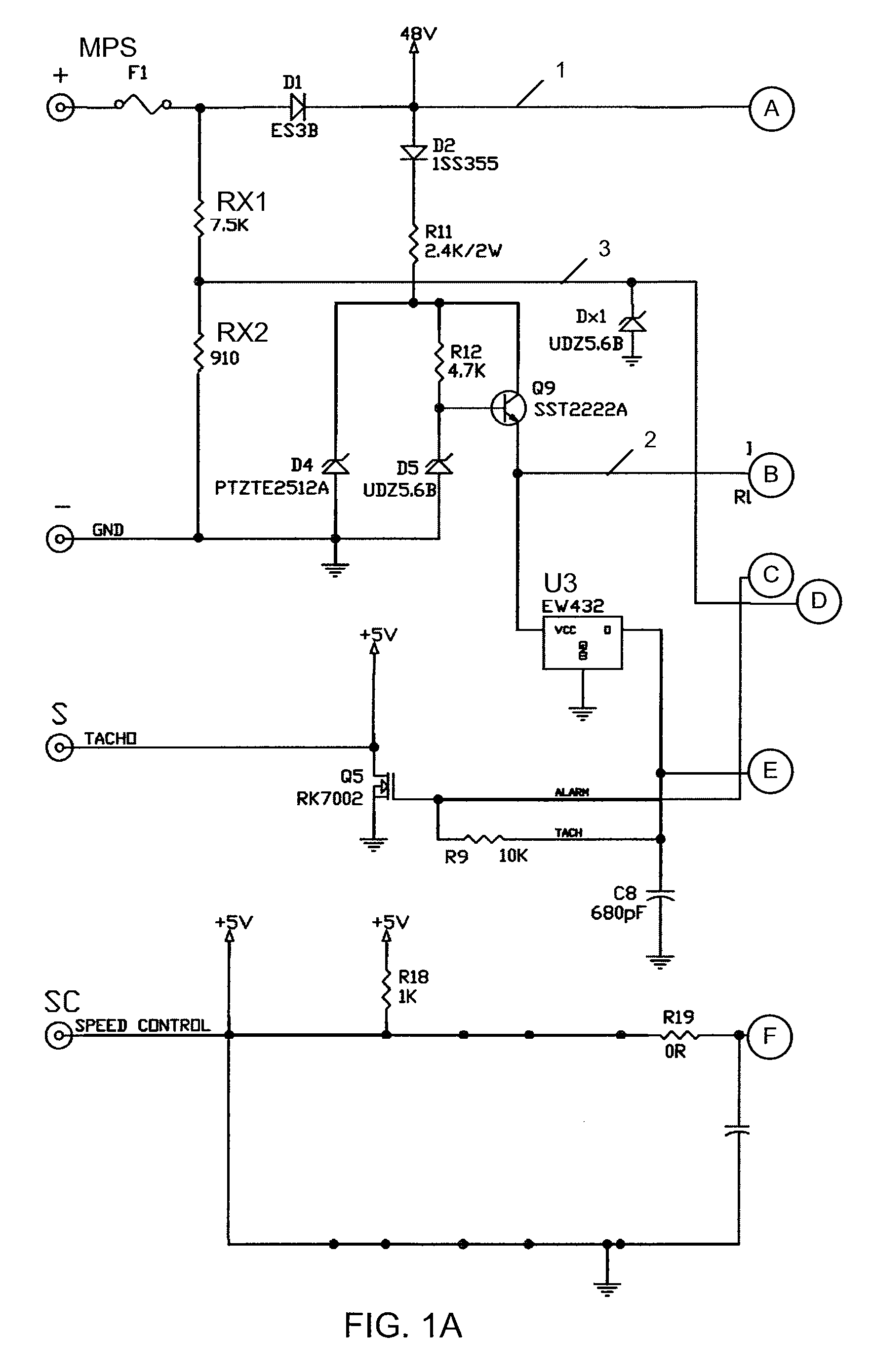
[0020]FIG. 1 is a schematic block diagram of an electronic system 10 using a microcontroller 200 for controlling a fan motor according to an embodiment of the present invention. This diagram is merely an illustrative example of electronic circuitry comprising the electronic system 10 according to the present invention which should not unduly limit the scope of the claims herein. One of ordinary skill in the art would recognize many variations, alternatives, and modifications. As shown, the electronic system 10 includes an H-bridge circuit 100 coupled to an input / output and power conditioning circuitry and a general purpose microcontroller 200 for intelligently driving or braking a fan motor M according to an embodiment of the invention. In the specific embodiment shown in FIG. 1, the microcontroller is manufactured and sold by Microchip Technology, Inc., part number PIC16F684. As for the H-bridge circuit 100, it would be understood by one of ordinary skill in the relevant motor arts...


PUM


Abstract

An electronic system for controlling a fan motor includes a microcontroller and a drive circuit. The microcontroller draws power from a first voltage source and generates control signals for sending drive current to stator coils of a fan motor via the drive circuit. The electronic system further includes a second voltage source to provide the microcontroller with an amount of energy sufficient to operate for a short period of time when the voltage of the first voltage source drops below a predetermined level. The microcontroller is configured to detect when the voltage level of the first voltage source drops below a given level and generates control signals for the drive circuit to discharge energy in the stator coils of the fan motor to quickly stop operation of the fan motor within a short period of time.

Description

BACKGROUND OF THE INVENTION[0001]The invention is directed to a method and apparatus for intelligently stopping a fan motor. Merely by way of example, the invention has been applied to techniques of using a microcontroller to control braking the fan motor whenever a main power supply is on or off. But it would be recognized that the invention has a much broader range of applicability.[0002]In electronic systems, such as computer systems or telecommunication systems, cooling fans are widely used for maintaining system operational capabilities. Because of the complexity of these electronic systems, cooling fans not only need to perform the traditional function of providing cooling air, but also need to have some intelligence in order to provide a user with specialized control of the fan motors. A typical conventional modern fan motor is of a type known as a brushless DC motor. Such a motor includes, among other things, a stator coil coupled to a DC power supply for inductively driving...

Claims


Application Information

Patent Timeline
Patent Type & Authority Patents(United States)
IPC IPC(8): H02P6/00
CPCH02P3/22
Inventor FRANKEL, SCOTTBEST, CHRISTOPHER
Owner MINEBEAMITSUMI INC
Why Eureka
Try Eureka