Counterbalance mechanism for fold out ramp

a counterbalance mechanism and fold-out technology, applied in ambulance services, construction, gearing, etc., can solve the problem that the assembly of the ramp also has a counterbalan

Active Publication Date: 2011-09-20
ELEVATOR U DIV OF HOGAN MFG
View PDF88 Cites 14 Cited by
  • Summary
  • Abstract
  • Description
  • Claims
  • Application Information

AI Technical Summary

Benefits of technology

A second ramp assembly has a ramp portion configured for reciprocating motion between a stowed position, a deployed position, and a neutral position. The ramp assembly also has a counterbalance, which includes a pin that moves along an arcuate path when the ramp portion moves between the stowed position and the deployed position moves the pin. The counterbalance further includes a rod and an end fitting coupled to a first end of the rod. The end fitting includes a recess for engaging the pin. A cylinder is coupled to a second end of the rod and is also coupled for rotational movement about an axis having a fixed location relative to the neutral position of the ramp portion. The cylinder provides a force to maintain engagement of the pin to the recess and to bias the ramp portion toward the stowed position when the ramp portion is between the deployed position and the neutral position, and toward the deployed position when the ramp portion is between the stowed position and the neutral position.

Problems solved by technology

The ramp assembly also has a counterbalance, which includes a pin that moves along an arcuate path when the ramp portion moves between the stowed position and the deployed position moves the pin.

Method used


Image

  • Counterbalance mechanism for fold out ramp
  • Counterbalance mechanism for fold out ramp
  • Counterbalance mechanism for fold out ramp

Examples


Embodiment Construction

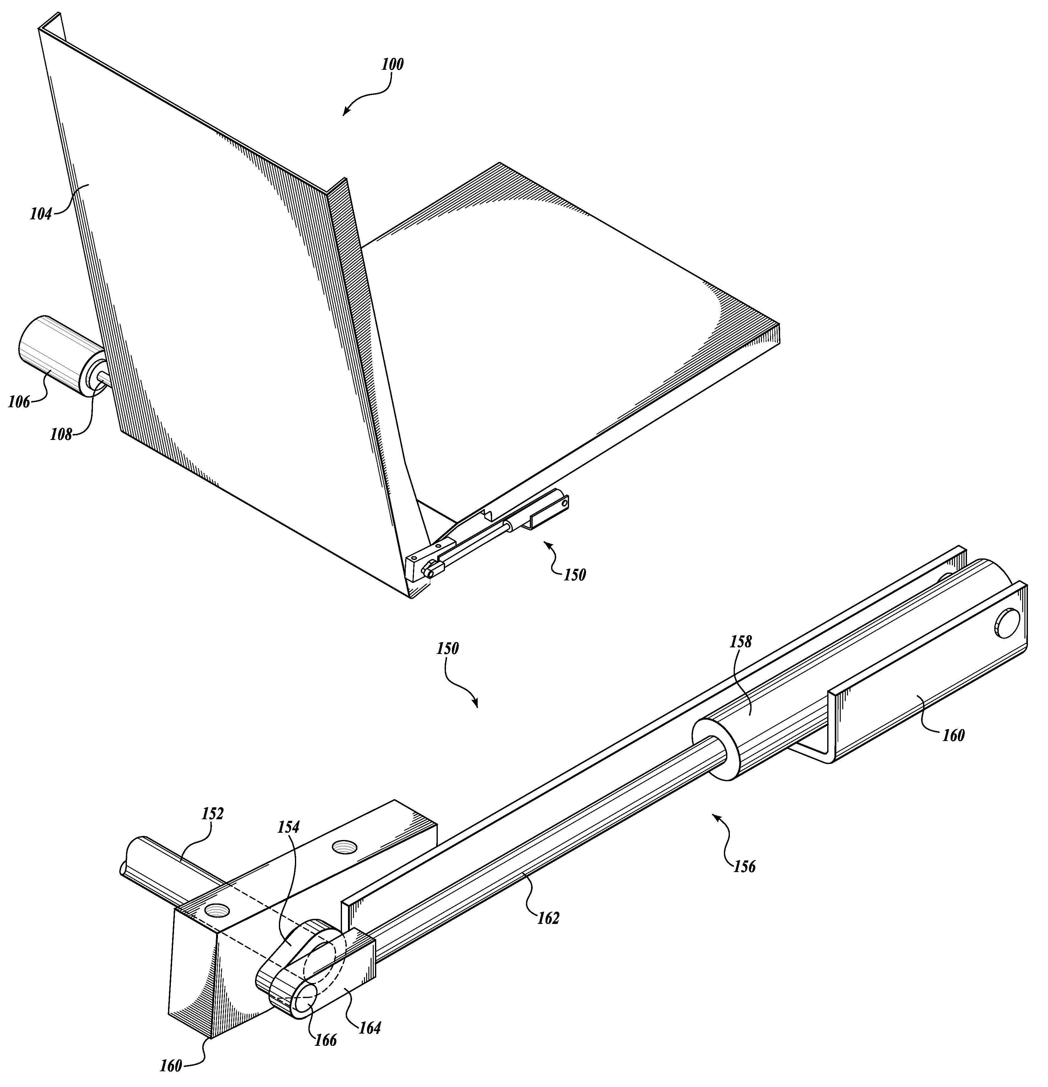
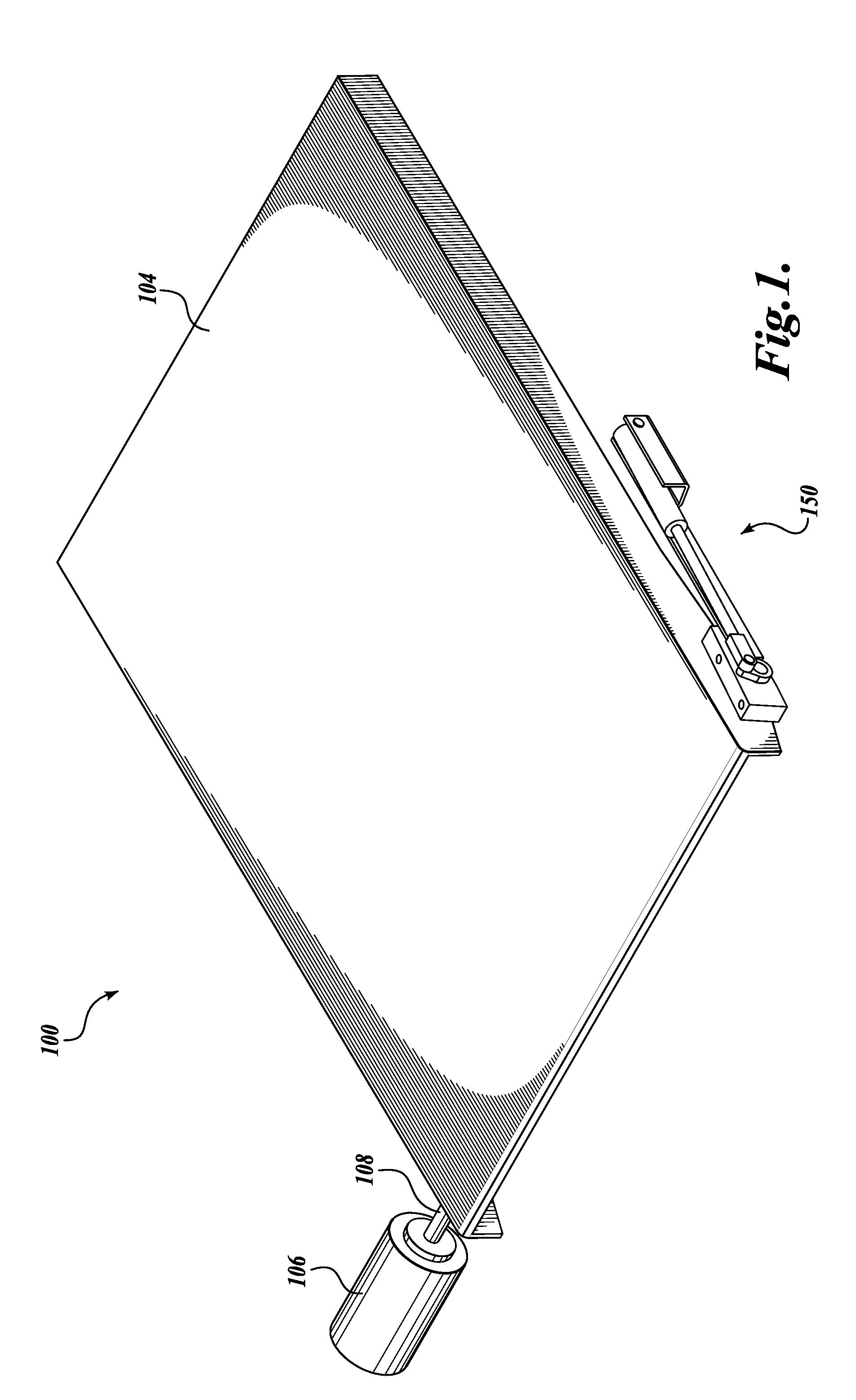
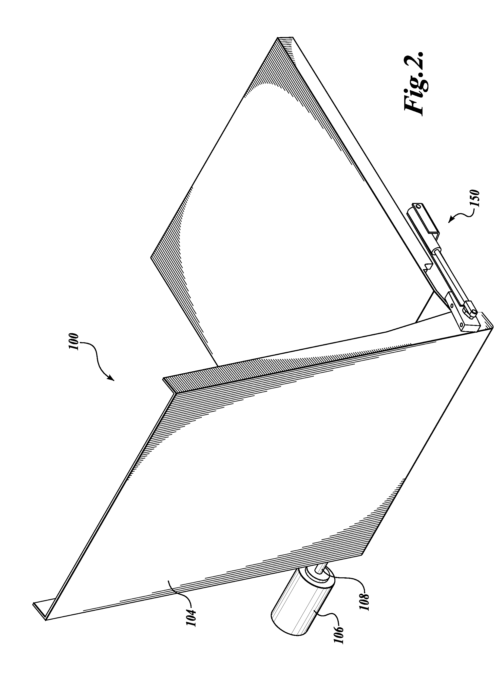
Exemplary embodiments of the present invention will now be described with reference to the accompanying drawings where like numerals correspond to like elements. Exemplary embodiments of the disclosed subject matter are directed to ramp assemblies, and in particular, to wheelchair ramp assemblies. In particular, described embodiments are directed to wheelchair ramp assemblies suitable for use in buses, vans, etc.

The following discussion proceeds with reference to examples of wheelchair ramp assemblies for use in vehicles having a floor, such as a bus, van, etc. While the examples provided herein have been described with reference to their association with vehicles, it will be apparent to one skilled in the art that this is done for illustrative purposes and should not be construed as limiting the scope of the claimed subject matter. Thus, it will be apparent to one skilled in the art that aspects of the present disclosure may be employed with other ramp assemblies used in stationary...


PUM


Abstract

A ramp assembly includes a ramp portion configured for reciprocating motion between a stowed position, a deployed position, and a neutral position. The ramp assembly further includes a counterbalance that provides a force to bias the ramp portion toward the stowed position when the ramp portion is between the deployed position and the neutral position, and toward the deployed position when the ramp portion is between the stowed position and the neutral position. A shaft rotates in a first direction when the ramp portion moves toward the stowed position, and in a second direction opposite the first direction when the ramp portion moves toward the deployed position. A crank is fixedly coupled to the shaft. A rod is rotatably coupled at a first end to the crank about a first axis and at a second end to a cylinder. The cylinder is coupled for rotational movement about a second axis.

Description

BACKGROUNDThe Americans with Disabilities Act (ADA) requires the removal of physical obstacles to those who are physically challenged. The stated objective of this legislation has increased public awareness and concern over the requirements of the physically challenged. Consequentially, there has been more emphasis in providing systems that assist such a person to access a motor vehicle, such as a bus or minivan.A common manner of providing the physically challenged with access to motor vehicles is a ramp. Various ramp operating systems for motor vehicles are known in the art. Some slide out from underneath the floor of the vehicle and tilt down. Others are stowed in a vertical position and are pivoted about a hinge, while still others are supported by booms and cable assemblies. The present invention is generally directed to a “fold out” type of ramp. Such a ramp is normally stowed in a horizontal position within a recess in the vehicle floor, and is pivoted upward and outward to a...

Claims


Application Information

Patent Timeline
Patent Type & Authority Patents(United States)
IPC IPC(8): E01D1/00
CPCA61G3/061Y10T74/1828A61G2003/067A61G3/067
Inventor JOHNSON, DAVIDCOHN, ALAN
Owner ELEVATOR U DIV OF HOGAN MFG
Why Eureka
Try Eureka