
Device and method for fastening balancing weights to rotors, in particular to propeller shafts or cardan shafts

Active Publication Date: 2007-07-31
SCHENCK ROTEC GMBH
View PDF14 Cites 13 Cited by
  • Summary
  • Abstract
  • Description
  • Claims
  • Application Information

AI Technical Summary

Benefits of technology

[0004]The object of the invention is to allow a simple and inexpensive application of the requisite balancing weights in a device and a method of the type mentioned at the outset.
[0006]Fully automatic compensation of imbalances is easily possible with the invention, wherein all balancing weights for complete compensation of imbalances of a rotor are fastened to the rotor by means of just one gripper-like device, without intermediate provision of balancing weights being necessary. This also includes a second supplementary imbalance compensation step which may possibly be necessary and which takes place in a compensation plane of the rotor closely adjacent in the longitudinal direction thereof. The gripper-like device can advantageously be equipped with balancing weights at just one suitable loading station. This can take place by means of an automatic equipping device or else via the operator. The frequency and / or the duration of the equipping operation is reduced, so, for example, two balancing machines for propeller shafts or cardan shafts can be serviced by just one operator in quick succession. This applies in particular when only a single loading station is provided for equipping a plurality of balancing machines and this is ergonomically advantageously located, for example, between the balancing machines or is arranged at the ends thereof. Production costs are lower as a result of the lower complexity owing to only one gripper-like device and the simplification of equipping with balancing weights.
[0008]An embodiment of the invention in which the two gripper units can be jointly displaced along the rotor axis is very simple in construction.
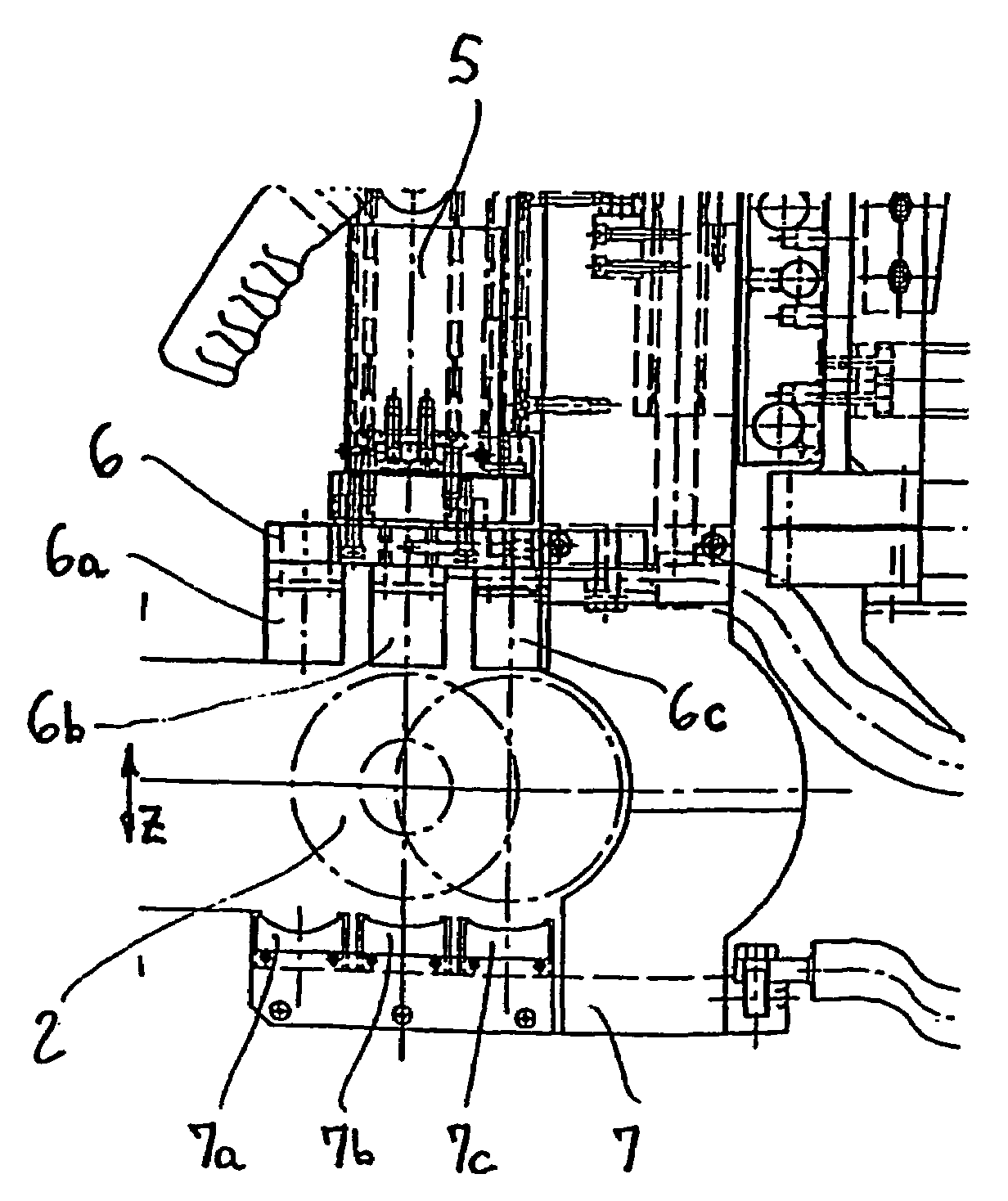
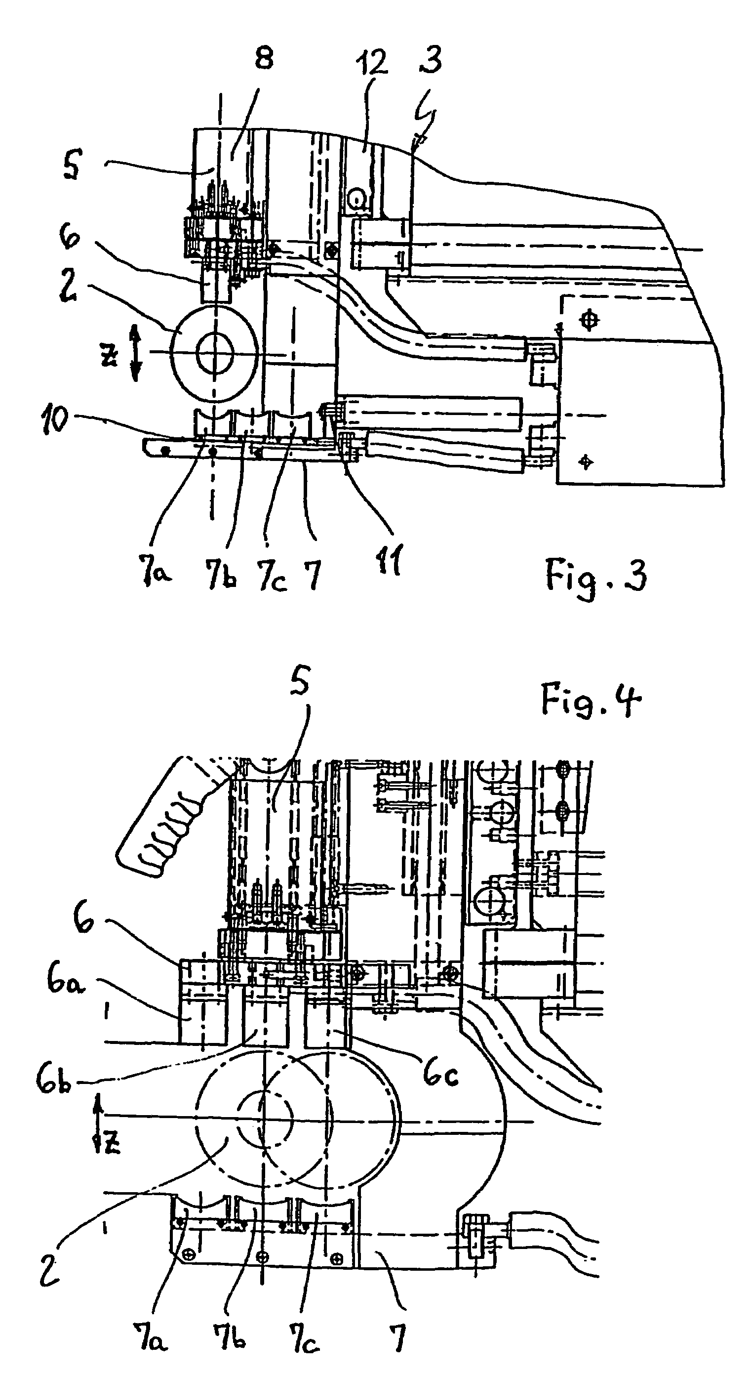
[0009]In an embodiment of the invention wherein the receiver part comprises receivers for balancing weights which are arranged in the manner of a matrix transversely to the longitudinal direction of the rotor and in the longitudinal direction of the rotor, it is possible to keep in stock different forms of balancing weight or different balancing weight materials, for example sheet steel or strips of sheet aluminium for welding-on. Rotors which are different in terms of form or material may also be balanced in mixed operation. The application, in other words the placing and subsequent fastening of the balancing weights, is further simplified by a configuration in which the receiver part and the other gripper unit are displaceable relative to each other in the longitudinal direction of the rotor and both can preferably be jointly displaced transversely to the longitudinal direction of the rotor as the receiver with the selected balancing weight and the counter element can thus be quickly arranged opposite each other on the other gripper unit.
[0010]A further advantageous configuration of the invention provides that preferably the lower gripper unit comprises receivers for balancing weights arranged one behind the other and transversely to the longitudinal direction of the rotor, with which receivers, in the gripper closing direction, respective counter elements are associated in a corresponding number on the other gripper unit. Aligned opposing counter elements are therefore associated with each receiver and the selection and application of the selected balancing weight are possible by simple joint displacement of the two gripper units transversely to the longitudinal axis of the rotor without movable components being required for this.

Problems solved by technology

Irrespective of whether one or more gripper-like devices are provided, there is expensive equipping of the gripper-like device with a balancing weight which is required at this balancing point for each balancing step.

Method used


Image

  • Device and method for fastening balancing weights to rotors, in particular to propeller shafts or cardan shafts
  • Device and method for fastening balancing weights to rotors, in particular to propeller shafts or cardan shafts
  • Device and method for fastening balancing weights to rotors, in particular to propeller shafts or cardan shafts

Examples


Embodiment Construction

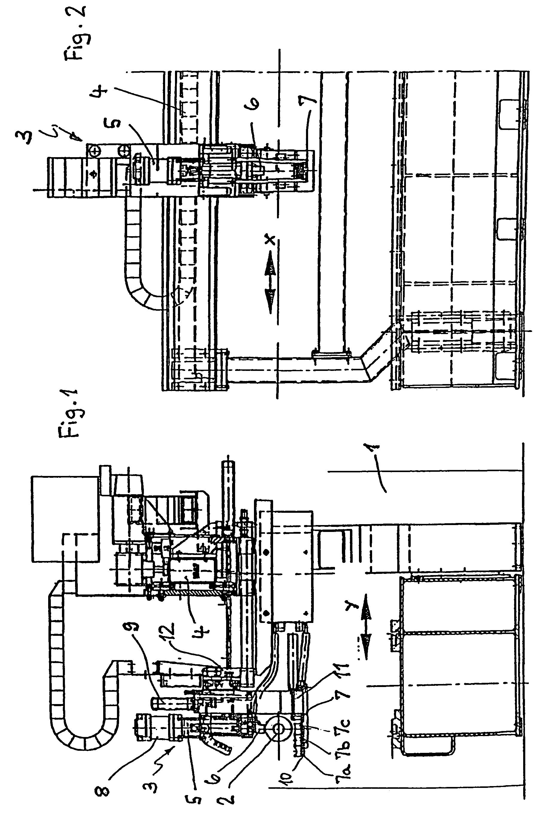
[0022]FIG. 1 schematically shows a balancing machine 1 in which a rotor 2 to be balanced is mounted. The balancing machine 1 comprises bearing devices (not shown in greater detail) for the rotor 2 to be balanced, at least one rotary drive, sensors for detecting the rotational behavior of the rotor 2 and of imbalance-induced vibrations and an evaluation device for ascertaining the imbalance of the rotor 2. A device 3 for fastening balancing weights in a plurality of compensation planes of the rotor 2 is also arranged on the balancing machine 1.

[0023]In the x direction of a right angle coordinate system, as is symbolized in FIG. 2 by the double arrow x, the device 3 can be displaced on a guide rail 4 arranged on the frame of the balancing machine 1, along the axis of the rotor which, in the illustration of FIG. 2, is located in the plane of the page. The guide rail 4 spans the balancing machine in the longitudinal direction of the rotor and is provided offset at the back, relative to ...


PUM


Abstract

In a device (3) for fastening balancing weights to rotors (2) with a plurality of compensation planes, in particular to propeller shafts or Cardan shafts, preferably in a balancing machine (1) that includes at least one gripper-like device which can be positioned along the rotor axis, and with which a balancing weight is placed on the external periphery of the rotor (2) and can be fastened there, the gripper-like device (5) includes plural receivers for receiving a plurality of the balancing weights.

Description

FIELD OF THE INVENTION[0001]The invention relates to a device for fastening balancing weights to rotors comprising a plurality of compensation planes, in particular to propeller shafts or cardan shafts, preferably in a balancing machine which comprises at least one gripper-like device which can be positioned along the rotor axis, with which device a balancing weight can be placed on the outer periphery of the rotor and fastened there, and to a method for fastening balancing weights to rotors by means of the gripper-like device.BACKGROUND INFORMATION[0002]Devices and methods of the type mentioned at the outset are used in series production to economically balance relatively large unit numbers of rotors which comprise a plurality of compensation planes, for example propeller shafts or cardan shafts.[0003]It is known from DE 44 40 812 A1 to arrange a rotor, for example a cardan shaft, in a balancing machine, to ascertain the imbalance in terms of size and angular position and to then p...

Claims


Application Information

Patent Timeline
IPC IPC(8): G01M1/02G01M1/38G01M1/32
CPCG01M1/32
Inventor ROGALLA, MARTINHILLRINGHAUS, FRANK
Owner SCHENCK ROTEC GMBH
Learn More