Laser Material Processing System

a material processing system and laser technology, applied in the field of material processing systems, can solve the problems of low average power of ultrafast laser pulses, high cost, and limitations of conventional nanosecond laser breakdown spectroscopy, and achieve the effects of improving laser pulse performance, less expensive, and broad bandwidth

Active Publication Date: 2009-07-30
BOARD OF TRUSTEES OPERATING MICHIGAN STATE UNIV
View PDF126 Cites 64 Cited by
  • Summary
  • Abstract
  • Description
  • Claims
  • Application Information

AI Technical Summary

Benefits of technology

[0006]In accordance with the present invention, a laser material processing system and method are provided. A further aspect of the present invention employs a laser for micromachining. In another aspect of the present invention, the system uses a hollow waveguide. In yet another aspect of the present invention, a laser beam pulse is given broad bandwidth for workpiece modification. A further aspect of the present invention allows a single laser beam to simultaneously operate in multiple machining workstations and / or to machine multiple holes in the same workpiece. Additionally, a system includes a laser, pulse shaper and compensation device, and control system, with another aspect of the present invention. In a further aspect of the present invention, a system employs Multiphoton Intrapulse Interference Phase Scan to improve laser pulse performance. A method of operating a laser for micromachining is also provided.
[0007]The present invention is advantageous over conventional constructions since the equipment or the processing throughput used in the system of the present invention is significantly less expensive than traditional equipment. Furthermore, multiple workstations can be simultaneously powered by a single laser, thereby reducing the laser expense per workpiece. The novel waveguide of the present invention system also beneficially increases ps or fs pulse bandwidth so a less expensive, longer pulse lasers can be employed while improving micromachining efficiency. For another exemplary advantage, an inexpensive picosecond laser of the present invention, directly pumped by a flash lamp, is employed in some variations instead of considerably more expensive conventional femtosecond lasers, pumped by green laser sources; nevertheless, the present invention system provides the functional advantages of femtosecond ablation of the workpiece, in part, due to enhancing the laser pulse bandwidth instead of reducing the pulse duration. Multiphoton Intrapulse Interference Phase Scan and binary pulse shaping are further beneficial in accurately and inexpensively controlling ps or fs laser pulses for micromachining. The present invention advantageously uses laser induced breakdown spectroscopy with shaped pulses and / or MIIPS optimization, and with or without chirped pulses, for feedback and closed loop control of micromachining; the LIBS signal can provide an atomic signature of each workpiece layer when stacked so as to provide sensed feedback when each layer is completely penetrated whereby the controller automatically varies the process accordingly. Additional advantages and features of the present invention will become apparent from the following description and appended claims, taken in conjunction with the accompanying drawings.

Problems solved by technology

The technology that makes these ultrafast laser pulses does not produce high average power.
Additionally, the technology is VERY expensive .
Furthermore, conventional nanosecond laser induced breakdown spectroscopy suffers some limitations due to inefficient coupling of the laser pulse energy into a sample.
The inefficient coupling requires high energies per pulse, typically in the 10-100 mJ / pulse range, and leaves a scar caused by melting.

Method used


Image

  • Laser Material Processing System
  • Laser Material Processing System
  • Laser Material Processing System

Examples


Embodiment Construction

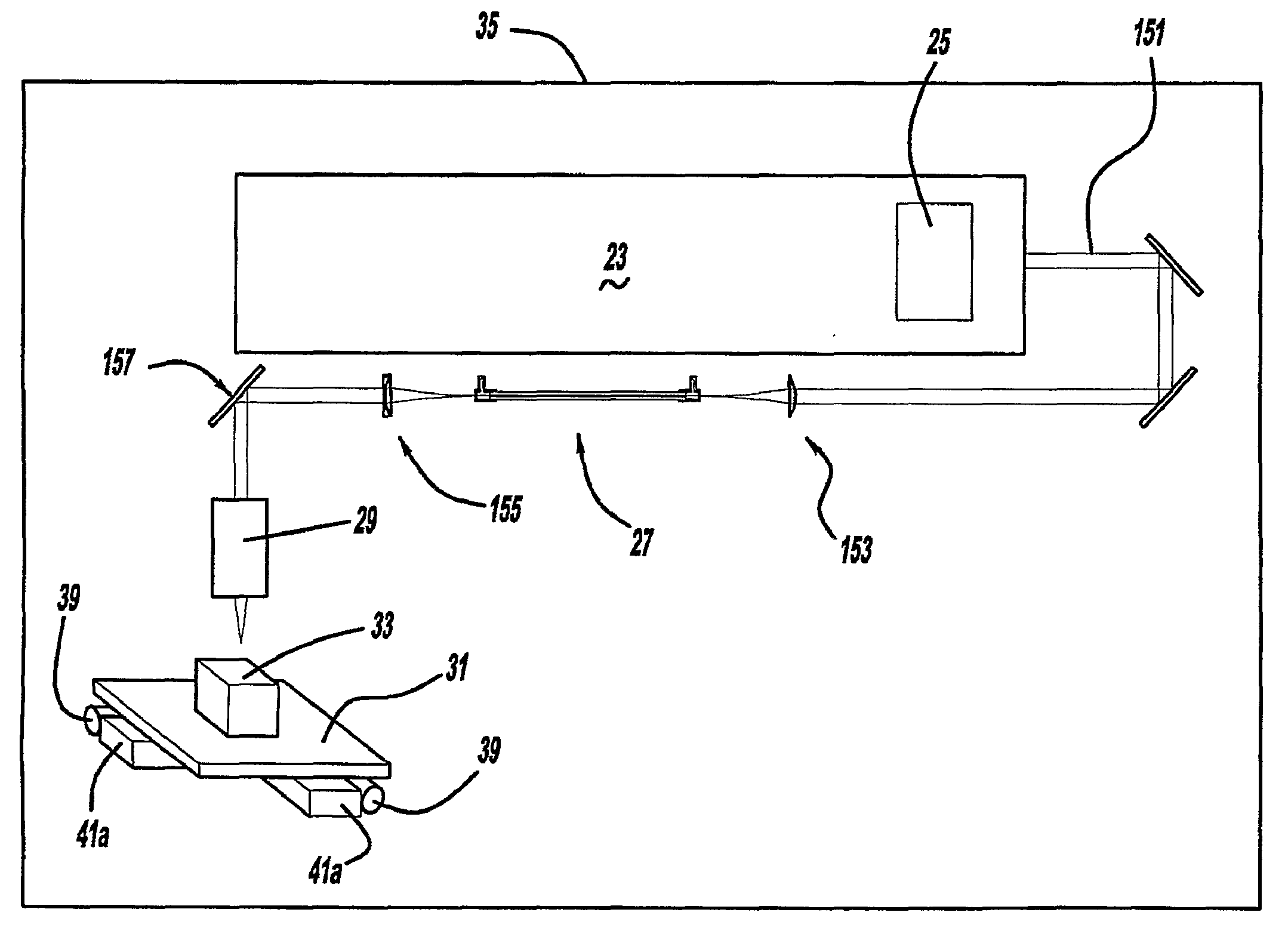
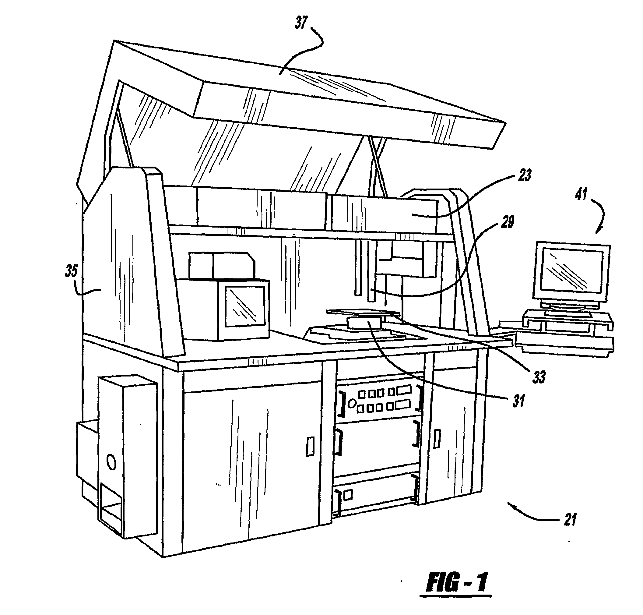
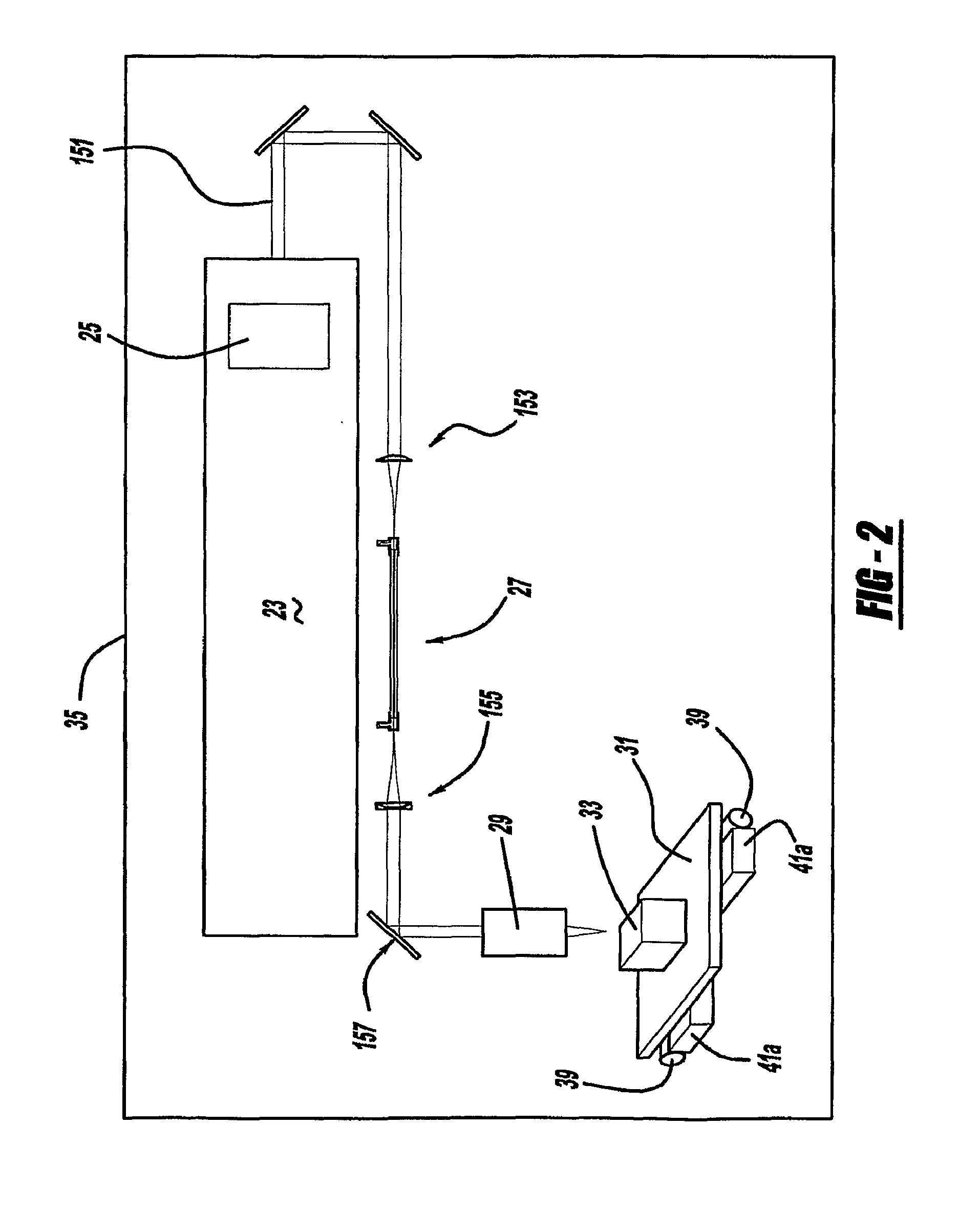
[0022]A first preferred embodiment of a laser material processing system 21 of the present invention is generally shown in FIGS. 1 and 2. System 21 includes a femtosecond laser 23, a pulse shaping and optimization system 25, a waveguide 27, an objective 29, a moveable table or workpiece-support 31, and a workpiece 33, inside a housing or cabinet 35 with an openable door 37. Table 31 is automatically moveable in at least X and Y directions, and optionally in an additional Z and / or rotational direction, by linear slides 41a and connected electric motors 39, controlled by a programmable, microprocessor-based computer controller 41. The present invention system is used for micromachining the workpiece, including drilling holes, cutting slots, polishing and the like.

Pulse Shaping and Optimization

[0023]Referring to FIGS. 3 and 4, pulse shaping and optimization system 25 includes an upstream grating 43, an upstream concave mirror 45, a spatial light modulator 47, a downstream concave mirro...


PUM


Abstract

A laser material processing system and method are provided. A further aspect of the present invention employs a laser for micromachining. In another aspect of the present invention, the system uses a hollow waveguide. In another aspect of the present invention, a laser beam pulse is given broad bandwidth for workpiece modification.

Description

CROSS REFERENCE TO RELATED APPLICATION[0001]This application claims priority to U.S. provisional patent application Ser. No. 60 / 790,695, filed on Apr. 10, 2006, which is incorporated by reference herein.STATEMENT OF GOVERNMENT INTEREST[0002]A portion of this invention was made with Government support under Contract No. DE-FG02-01 ER15143 awarded by the Department of Energy. The Government may have certain rights in this invention.BACKGROUND AND SUMMARY OF THE INVENTION[0003]The present invention generally relates to a material processing system and more particularly to micromachining with a laser.[0004]It is known to employ femtosecond lasers for micromachining. The use of these ultrafast lasers has significantly improved the machining efficiency by quickly removing the workpiece material due to the instantaneous increase of the material temperature into a plasma regime. Furthermore, ionization of the material reduces splatter and debris during operation. An exemplary conventional d...

Claims


Application Information

Patent Timeline
Patent Type & Authority Applications(United States)
IPC IPC(8): B23K26/067G02F1/295B23K26/00B23K26/08
CPCB23K26/032B23K26/4075B23K26/0639B23K26/0665B23K26/067B23K26/0673B23K26/0676B23K26/0853B23K26/365B23K26/381B23K26/383B23K26/4005B23K26/401B23K26/402B23K26/403B23K26/4065H01S3/0057B23K26/1429B23K26/4025B23K26/0635B23K26/40B23K26/064B23K26/382B23K26/0624B23K26/384B23K26/361B23K2103/54B23K2103/08B23K2103/42B23K2103/50B23K26/348
Inventor DANTUS, MARCOS
Owner BOARD OF TRUSTEES OPERATING MICHIGAN STATE UNIV
Why Eureka
Try Eureka