
Two-station rotator drilling de-weight full-automatic balance machine

A balancing machine and two-station technology, applied in the field of balancing machines, can solve problems such as complex processing steps, complex overall structure, and low processing efficiency, and achieve the effects of reduced processing costs, simple overall structure, and improved processing efficiency

Inactive Publication Date: 2015-03-11
上海剑平动平衡机制造有限公司
View PDF4 Cites 13 Cited by
  • Summary
  • Abstract
  • Description
  • Claims
  • Application Information

AI Technical Summary

Problems solved by technology

[0004] The above-mentioned five-station motor rotor balancing machine in the prior art has the advantages that the balancing machine realizes automatic balancing detection, removes weight from cutting, improves processing efficiency, and has good processing stability; however, its disadvantages are: the balancing machine consists of It consists of five stations, among which the detection of the motor rotor needs to be completed by the initial measurement balance device and the re-measurement balance device, and the cutting and weight removal of both ends of the motor rotor needs to be completed by two cutting slides, and its overall structure is relatively complicated. The processing cost is high, and the overall volume is large, taking up a lot of space. At the same time, in the detection and cutting weight removal device of the balancing machine, there is no adjustment mechanism for different sizes of products of different models, so that it can only process specific A product with poor compatibility, in addition, its processing steps are more complicated, resulting in lower processing efficiency

Method used


Image

  • Two-station rotator drilling de-weight full-automatic balance machine
  • Two-station rotator drilling de-weight full-automatic balance machine
  • Two-station rotator drilling de-weight full-automatic balance machine

Examples


Embodiment Construction

[0025] An embodiment of the present invention will be described in detail below in conjunction with the accompanying drawings.

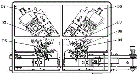
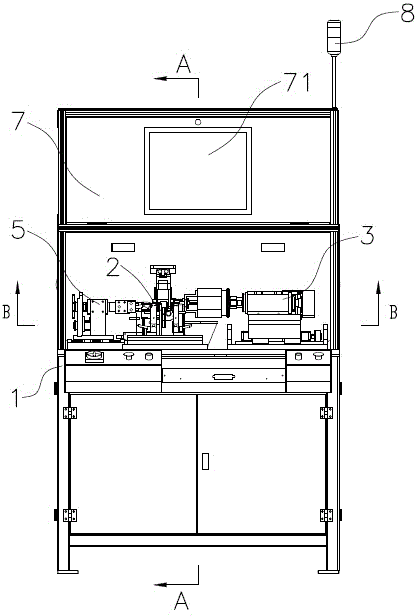
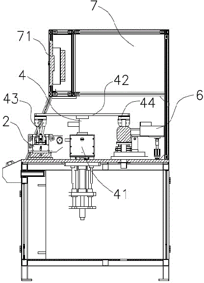
[0026] Such as Figure 2 ~ Figure 4 As shown, the two-station rotor drilling weight removal automatic balancing machine of the embodiment of the present invention includes a frame 1, a balance measurement positioning mechanism 2, a drilling mechanism 3, a mechanical rotating arm 4, a corner mechanism 5, and a pressing and reversing mechanism 6. The control cabinet 7 and the alarm device 8, the mechanical rotating arm 4 is installed on the frame 1 adjacent to the middle position, the balance measurement and positioning mechanism 2 is arranged under one end of the mechanical rotating arm 4, and the pressing reversing mechanism 6 is arranged on the mechanical rotating arm 4 Below the other end, the drilling mechanism 3 is installed on the frame 1, the drilling end of the drilling mechanism 3 corresponds to the pressing position of the compression revers...


PUM


Abstract

The invention disclose a two-station rotator drilling de-weight full-automatic balance machine. The two-station rotator drilling de-weight full-automatic balance machine comprises a machine frame, a balance measuring positioning mechanism, a drilling mechanism, a mechanical rotary ram, a corner mechanism and a compressing and reversing mechanism, wherein the mechanical rotary arm is mounted at the position near the central part of the machine frame; the balance measuring positioning mechanism is arranged below one end part of the mechanical rotary arm; the compressing and reversing mechanism is arranged below the other end of the mechanical rotary arm; the drilling mechanism is mounted on the machine frame; the drilling end of the drilling mechanism corresponds to the compressing position of the compressing and reversing mechanism; the corner mechanism is mounted on the machine frame; the corner mechanism and the drilling mechanism are respectively positioned on the two sides of the compressing and reversing mechanism. The full-automatic balance machine has the advantages that the overall structure is simple; the machining cost is greatly reduced; the size is small; the occupied space is reduced; meanwhile, the machining requirements of a variety of products can be met; the compatibility is high; moreover, due to the mechanical rotary arm and the compressing and reversing mechanism, product machining stations can be switched more quickly, so that the machining efficiency is greatly improved.

Description

technical field [0001] The invention relates to a balancing machine, in particular to a two-station rotor drilling and weight-removing automatic balancing machine. Background technique [0002] Balancing machines are widely used in the motor industry, especially in manufacturers of micro motors, water pump motors, electric tools, small household appliances, automotive motors, and fractional horsepower motors. Most of these companies use general-purpose balancing machines, rely on a single machine for balancing machine testing, and use manual corrections. The balancing efficiency and balancing accuracy are restricted by some shortcomings of the balancing equipment. In order to meet the needs of output, coupled with the rise of production costs, especially the rise of labor costs in recent years, it has reached the point where the needs of enterprises cannot be met by increasing the number of single machines alone. And if the traditional method can only be compensated by incr...

Claims


Application Information

Patent Timeline
IPC IPC(8): H02K15/16
Inventor 刘辉
Owner 上海剑平动平衡机制造有限公司
Learn More