Al technical title is built by PatSnap Al team. It summarizes the technical point description of the patent document.
a technology of non-articulation and wiper blade, which is applied in the direction of vehicle maintenance, vehicle cleaning, domestic applications, etc., can solve the problems of spring rail positioning and expected difficulties
Inactive Publication Date: 2011-09-20
ROBERT BOSCH GMBH
View PDF16 Cites 48 Cited by
Summary
Abstract
Description
Claims
Application Information
AI Technical Summary
This helps you quickly interpret patents by identifying the three key elements:
Problems solved by technology
Method used
Benefits of technology
[0007]According to the invention, the claw feet are bent around the narrow sides of the spring rails during the assembly of the sheet metal claws. In the process, at least one layer and / or an intermediate layer of plastic are provided between the claw feet on the one hand and the spring rails on the other hand, which layers are manufactured separately from the wiper strip and are adapted to the claw feet as well as have a high coefficient of friction on their surface towards the sheet metal claw and towards the spring rails. Because of the measures in accordance with the invention, the sheet metal claw can also be mounted easily and without additional welding or adhesion even with wiper blades with two spring rails. In this case, the spring rails can be grasped by a device and held at a desired distance by a spacer device. Since the intermediate layer is manufactured separately from the wiper strip and allocated and adapted to the claw feet, it can easily be placed on the spring rails before the wiper strip is mounted. As a result, first the sheet metal claw of the connecting device can be fixed on the spring rails and then the wiper strip can be slid between the spring rails.
[0014]According to an embodiment of the invention, the protuberance has at least two elevations. It is possible as a result to shift the elevations near the claw feet without the individual elevation having to be relatively large.
Problems solved by technology
During the assembly of the sheet metal claws, difficulties are to be expected, however, in the positioning of the spring rails if two spring rails that run essentially parallel are provided.
Method used
Image
Click on the blue label to locate the original text in one second.
Reading with bidirectional positioning of images and text.
Examples
Embodiment Construction
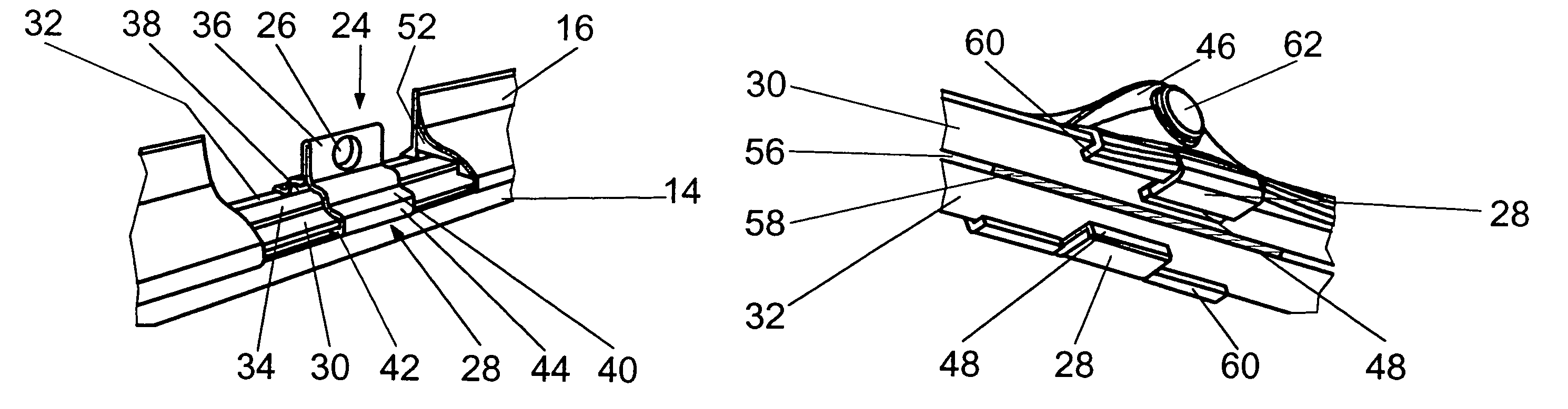
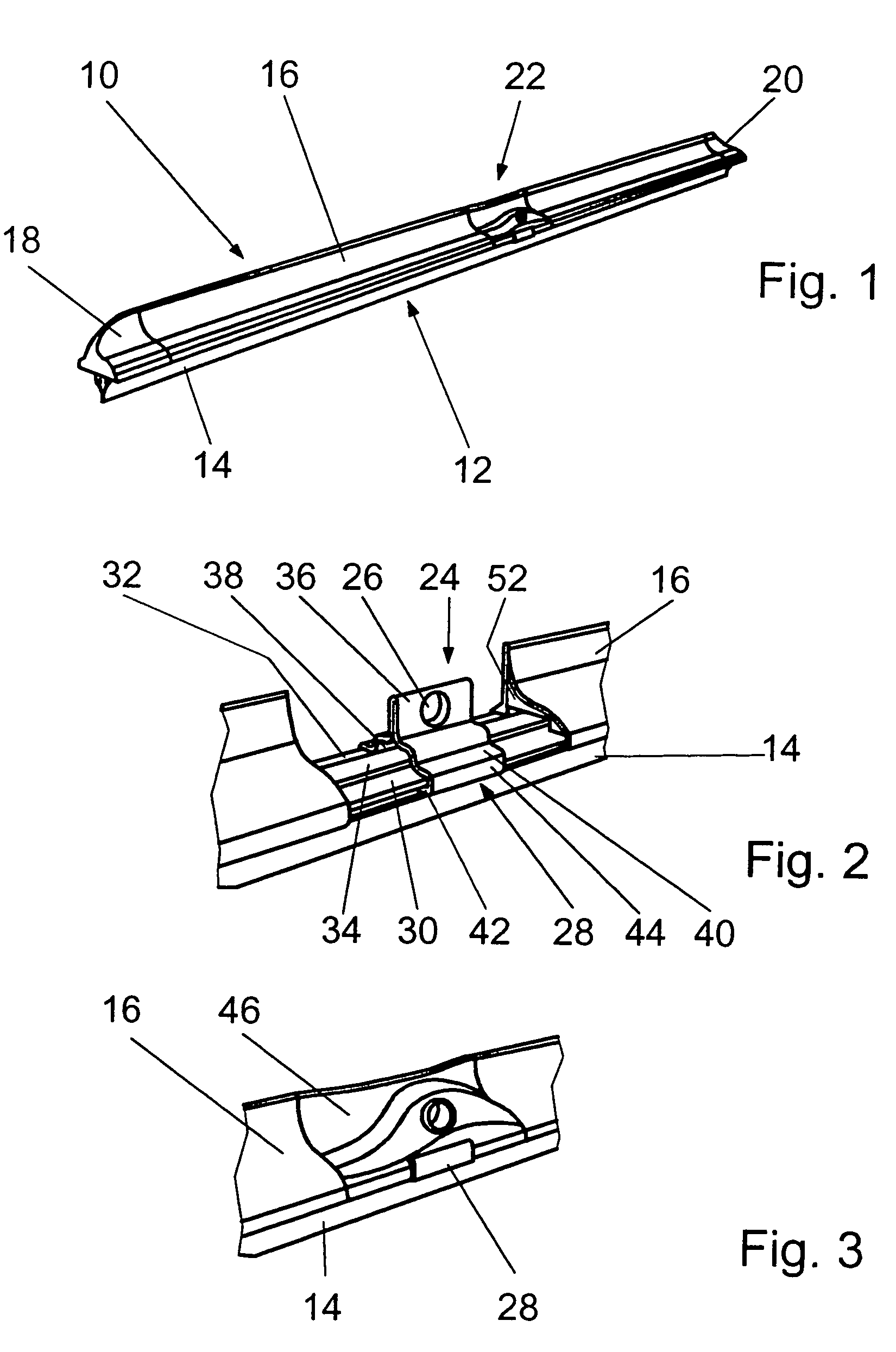
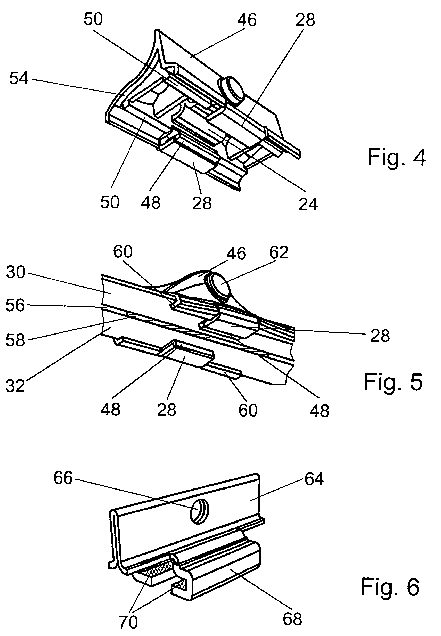
[0032]A non-articulated wiper blade 10 has essentially a wiper strip 12 with a wiper lip 14 and spoilers 16, on which end caps 18 and 20 are attached towards the ends. A connecting device 22 is provided in the center region of the wiper blade 10, through which the wiper blade 10 can be connected in an articulated manner to a wiper arm (not shown). The connecting device 22 has a sheet metal claw 24 (FIG. 2) and a plastic cap 46 (FIG. 3), which is clipped on the sheet metal claw 24 or on spring rails 30, 32. The spring rails 30, 32 form a supporting element for the wiper blade 10. They are preliminarily bent in such a way that in an unstressed state the wiper blade 10 has a considerably stronger curvature than a vehicle window for which it is intended. If the wiper blade 10 is pressed against the vehicle window by the wiper arm, a distribution of pressure that is suitable for the wiping process is produced over the length of the wiper blade 10.
[0033]The sheet metal claw 24 is formed f...
PUM
Abstract
A non-articulated wiper blade (10), which is constructed of a wiper strip (12) having a wiper lip (14), two spring rails (30, 32) and a connecting device (22), wherein the spring rails (30, 32) engage in lateral longitudinal grooves of the wiper strip (12) that are open towards the outside and are clasped by claw feet (28, 68, 76, 108) of a sheet metal claw (24, 64, 72, 106) of the connecting device (22) from an outer narrow side. The claw feet (28, 68, 76, 108) are bent around the narrow sides of the spring rails (30, 32) during the assembly of the sheet metal claws (24, 64, 72, 106), wherein at least one layer (70) and / or an intermediate layer (48, 84) of plastic are provided between the claw feet (28, 68, 76, 108) on the one hand and the spring rails (30, 32) on the other hand, which layers are manufactured separately from the wiper strip (12) and are adapted to the claw feet (28, 68, 76, 108) as well as have a high coefficient of friction on their surface towards the sheet metal claw (24, 64, 72, 106) and towards the spring rails (30, 32).
Description
BACKGROUND OF THE INVENTION[0001]The invention starts with a non-articulated wiper blade.[0002]A non-articulated wiper blade is known from DE 101 13 680 A1 whose wiper strip is comprised of an elastomer material and has a spoiler situated on its upper side. This spoiler can be formed on directly and be comprised of the same material as the wiper strip or be a separate component made of another suitable plastic. The spoiler can serve as a supporting element of the wiper blade by itself or together with spring rails, which are inserted into lateral longitudinal grooves of the profile of the wiper strip. Mounted on the ends of the wiper blade are caps, whose guide surfaces run in the longitudinal direction of the wiper blade and are adjacent with a slight shoulder to the guide surface of the spoiler. Because of the guide surfaces of the spoiler and the end caps, the air steam increasingly presses the wiper blade against the vehicle window with increasing vehicle speed if the air stream...
Claims
Application Information
Patent Timeline
Application Date:The date an application was filed.
Publication Date:The date a patent or application was officially published.
First Publication Date:The earliest publication date of a patent with the same application number.
Issue Date:Publication date of the patent grant document.
PCT Entry Date:The Entry date of PCT National Phase.
Estimated Expiry Date:The statutory expiry date of a patent right according to the Patent Law, and it is the longest term of protection that the patent right can achieve without the termination of the patent right due to other reasons(Term extension factor has been taken into account ).
Invalid Date:Actual expiry date is based on effective date or publication date of legal transaction data of invalid patent.