Wiper apparatus

a technology of wipers and arm pieces, which is applied in the field of wipers, can solve the problems of difficult to appropriately shape the arm pieces, affect the outer appearance of the wipers, and tend to be complicated in the formation of the arm pieces, so as to achieve sufficient rigidity of the arm pieces and eliminate undesired level differences

Inactive Publication Date: 2011-09-20
HONDA MOTOR CO LTD
View PDF5 Cites 39 Cited by
  • Summary
  • Abstract
  • Description
  • Claims
  • Application Information

AI Technical Summary

Benefits of technology

[0006]In view of the foregoing prior art problems, it is an object of the present invention to provide an improved wiper apparatus which can not only eliminate an undesired level difference between a distal end portion of an arm shank and an arm piece but also secure a sufficient rigidity of the arm piece.
[0008]In the wiper apparatus of the present invention, where the outer peripheral surface of the arm piece cover is flush with the outer peripheral surface of the distal end portion of the arm shank, no step or level difference is formed between the distal end portion of the arm piece cover and the arm shank, and thus, it is possible to provide a sense of unity or oneness between the arm piece cover and the arm shank and thereby significantly enhance the outer appearance of the wiper apparatus. Further, because the arm piece and the arm piece cover are formed as separate component parts, the arm piece can be significantly simplified in shape and thus can be readily formed of a material having a greater rigidity. With the arm piece formed of a high-rigidity material, it is possible to secure a sufficient rigidity of the arm piece and appropriately press the wiper blade against the window glass by means of the arm piece. In this way, the window glass can be appropriately wiped with the wiper blade.
[0009]In an embodiment, the arm piece cover has a cover body that covers a surface of the arm piece opposite from the window glass, and a side wall that extends from one of opposite side edges of the cover body to cover a side surface of the arm piece. In assembly of the wiper apparatus, the side wall of the arm piece cover is caused to abut against the side surface of the arm piece so that the cover can be positioned in a predetermined mounting position using the side wall. Thus, the arm piece cover can be readily positioned in the predetermined mounting position and attached to the arm piece with an increased ease. Further, by causing the side wall to abut against the side surface of the arm piece, the arm piece cover can be attached to the arm piece with an increased accuracy and increased stability.
[0010]In an embodiment, the side wall of the arm piece cover covers a front side surface, facing forward as viewed in a front-rear direction of the vehicle, of the arm piece. Thus, an air stream produced during travel of the vehicle (“traveling air stream”) can be received by the side wall, so that the arm piece cover can be reliably kept attached to the arm piece with an increased stability during travel of the vehicle.
[0012]In an embodiment, one end portion of the arm piece cover is held in end-to-end abutment against the distal end portion of the arm shank in an abutment region between the arm piece cover and the arm shank. The projecting wall section of the arm piece cover has, in a portion thereof adjacent to the distal end portion of the arm shank, a positioning portion and an expansion / contraction permitting portion located remoter than the positioning portion from the abutment region. The expansion / contraction permitting portion has an expansion / contraction margin for permitting thermal expansion / contraction of the arm piece cover in a longitudinal direction of the arm piece cover. The positioning portion permits accurate positioning of the arm piece cover, and the expansion / contraction permitting portion permits thermal expansion / contraction of the arm piece cover in the longitudinal direction.
[0013]In an embodiment, the arm piece is formed of a material of greater rigidity than the arm piece cover covering the arm piece. Thus, it is possible to effectively prevent the arm piece cover from undesirably swaying relative to the arm shank. Thus, it is possible to attach the arm piece cover to the arm shank with an increased sense of unity or oneness.

Problems solved by technology

Therefore, a step or level difference would be formed between the distal end portion of the arm shank and the arm piece, which impairs the outer appearance of the wiper apparatus.
However, with the wiper apparatus disclosed in the 2000-344057 publication, which requires a particular sectional shape of the arm piece, it is difficult to appropriately shape the arm piece.
Thus, formation of the arm piece tends to be complicated.
If the arm piece is formed of resin like this, however, a sufficient rigidity of the arm piece can not be secured, and as a consequence, the arm piece can not appropriately press the wiper blade against a window glass.
Therefore, the window glass can not be appropriately wiped with the wiper blade of the wiper apparatus.

Method used


Image

  • Wiper apparatus
  • Wiper apparatus
  • Wiper apparatus

Examples


Embodiment Construction

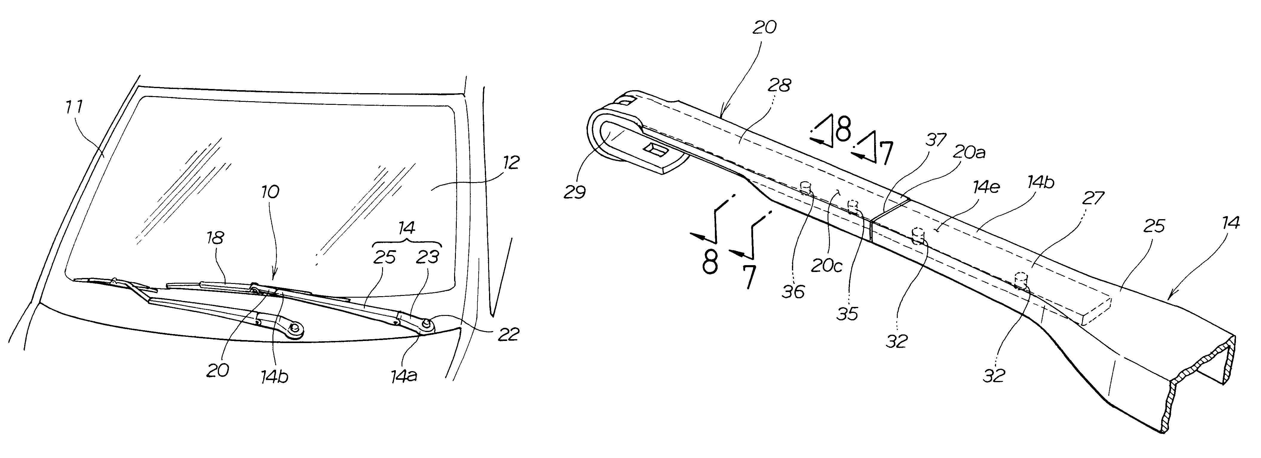
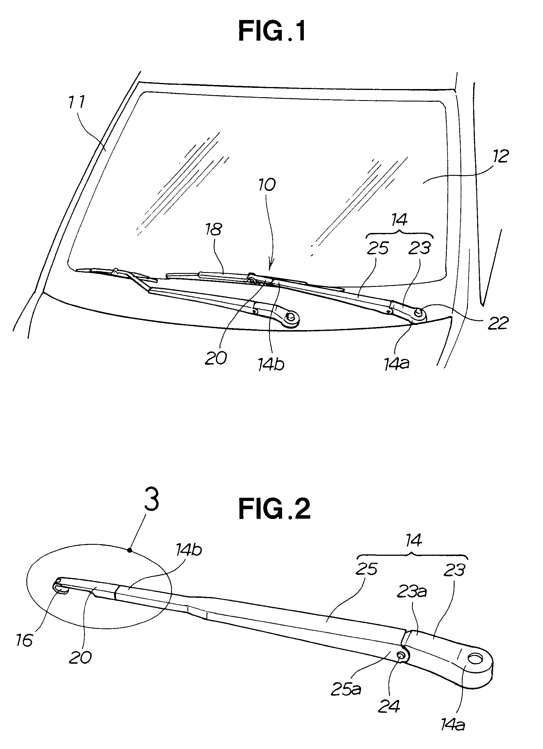
[0026]Reference is now made to FIG. 1 showing in perspective a vehicle provided with a wiper apparatus according to an embodiment of the present invention, and to FIG. 2 showing in perspective the wiper apparatus with a wiper blade removed therefrom. The wiper apparatus 10 is provided near a front window glass 12 of the vehicle 11 to wipe the window glass 12.

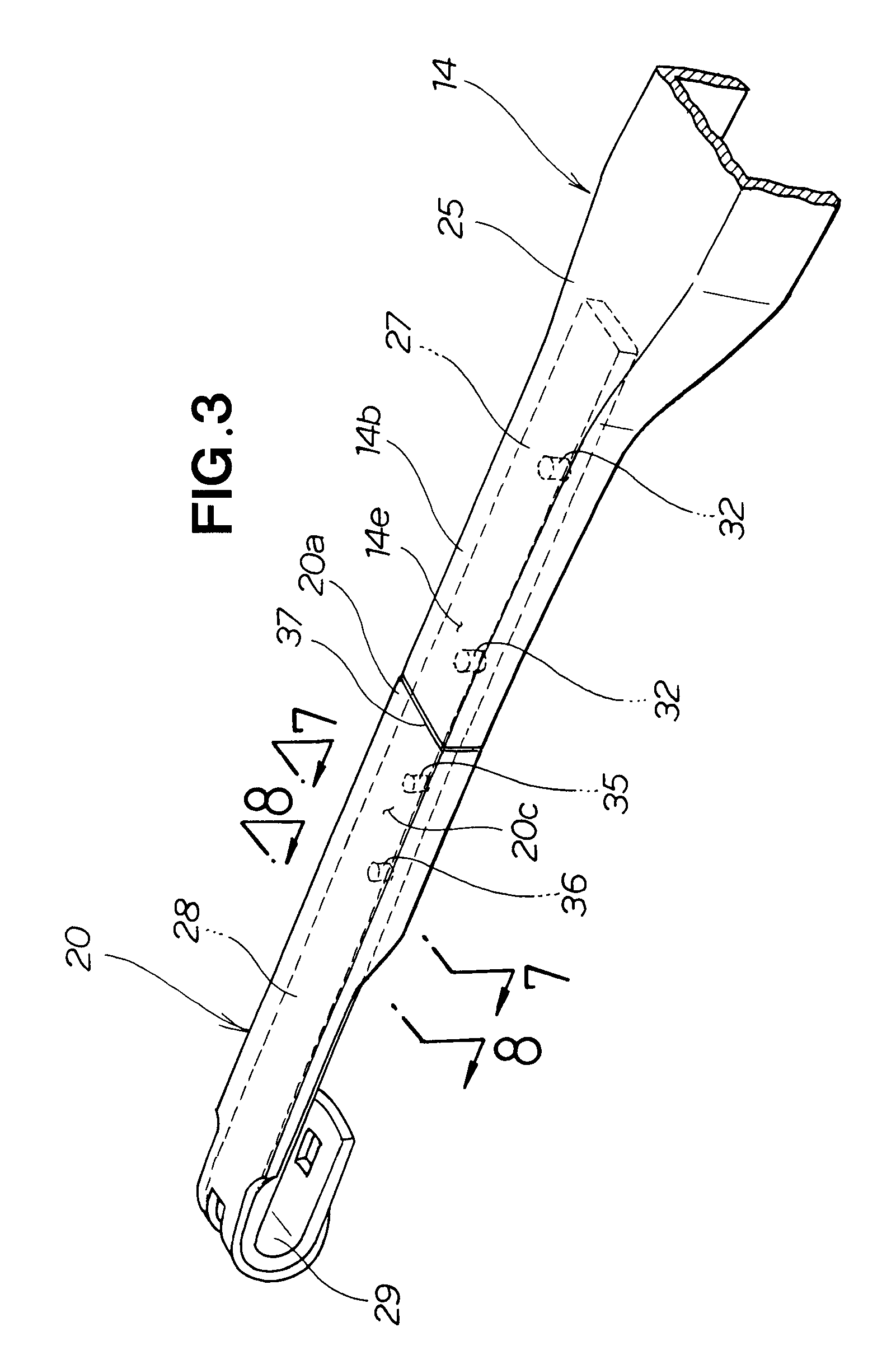
[0027]The wiper apparatus 10 includes an arm shank 14 pivotably supported at its proximal end portion 14a by the vehicle 11, an arm piece 16 mounted to a distal end portion 14b of the arm shank 14, a wiper blade 18 attached to the arm piece 16, and an arm piece cover 20 covering the arm piece 16.

[0028]The arm shank 14 includes a head 23 having the proximal end portion 14a pivotably supported on the vehicle 11 by means of a bolt 22, and a retainer 25 connected to a distal end portion 23a of the head 23 by means of a connection pin 24. The head 23 is pivotable about the bolt 22 along the front window glass 12. The retainer 25 is c...


PUM


Abstract

A wiper apparatus includes an arm shank pivotably supported at its proximal end portion on a vehicle and an arm piece mounted at its proximal end portion to a distal end portion of the arm shank and having a wiper blade attached to the other end portion remote from the distal end portion of the arm shank. The wiper apparatus also includes an arm piece cover covering the arm piece having an outer peripheral surface flush with an outer peripheral surface of the distal end portion of the arm shank.

Description

FIELD OF THE INVENTION[0001]The present invention relates to a wiper apparatus for wiping a vehicular window glass with a wiper blade.BACKGROUND OF THE INVENTION[0002]In wiper apparatus for vehicles, an arm shank is pivotably supported at its proximal end portion on a vehicle body, an arm piece is mounted to a distal end portion of the arm shank, and a wiper blade is mounted to the arm piece. Window glass is wiped with the wiper blade through pivoting movement of the ark shank.[0003]Generally, such wiper apparatus are mounted on a vehicle body with the arm piece swaged to a distal end portion of the arm shank. Therefore, a step or level difference would be formed between the distal end portion of the arm shank and the arm piece, which impairs the outer appearance of the wiper apparatus.[0004]To eliminate such an undesired level difference between the distal end portion of the arm shank and the arm piece, it has been proposed to form a sectional shape of the arm piece such that a por...

Claims


Application Information

Patent Timeline
Patent Type & Authority Patents(United States)
IPC IPC(8): B60S1/34
CPCB60S1/3429B60S1/3447B60S1/3431
Inventor MASUDA, TADASHIKAGAWA, MAMORU
Owner HONDA MOTOR CO LTD
Why Eureka
Try Eureka