Baseplate for use with bass drum

Inactive Publication Date: 2011-09-20
BURNS NICHOLAS R
View PDF6 Cites 12 Cited by
  • Summary
  • Abstract
  • Description
  • Claims
  • Application Information

AI Technical Summary

Problems solved by technology

Without these isolation mediums, the relative

Method used


Image

  • Baseplate for use with bass drum
  • Baseplate for use with bass drum
  • Baseplate for use with bass drum

Examples


Embodiment Construction

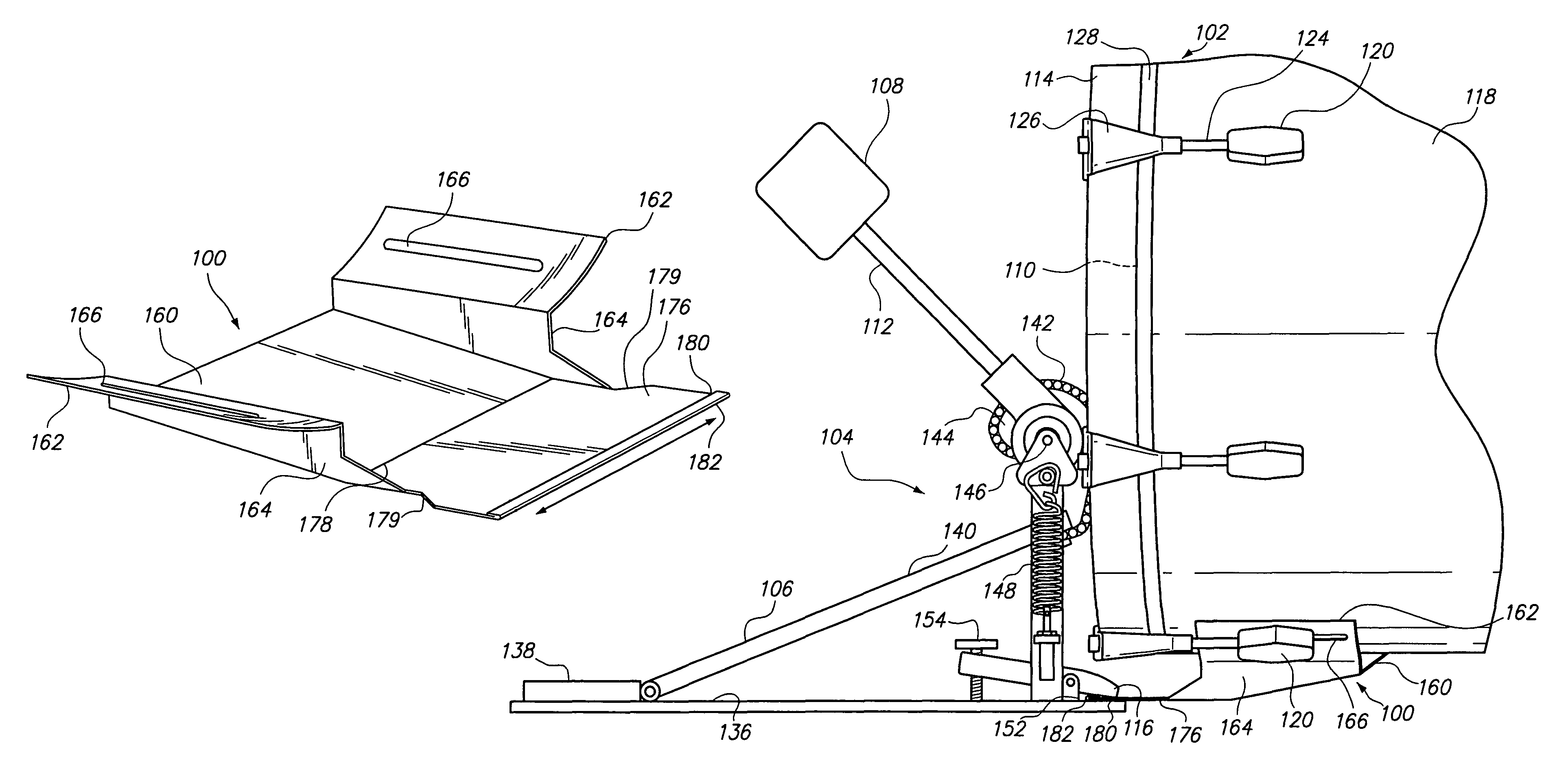
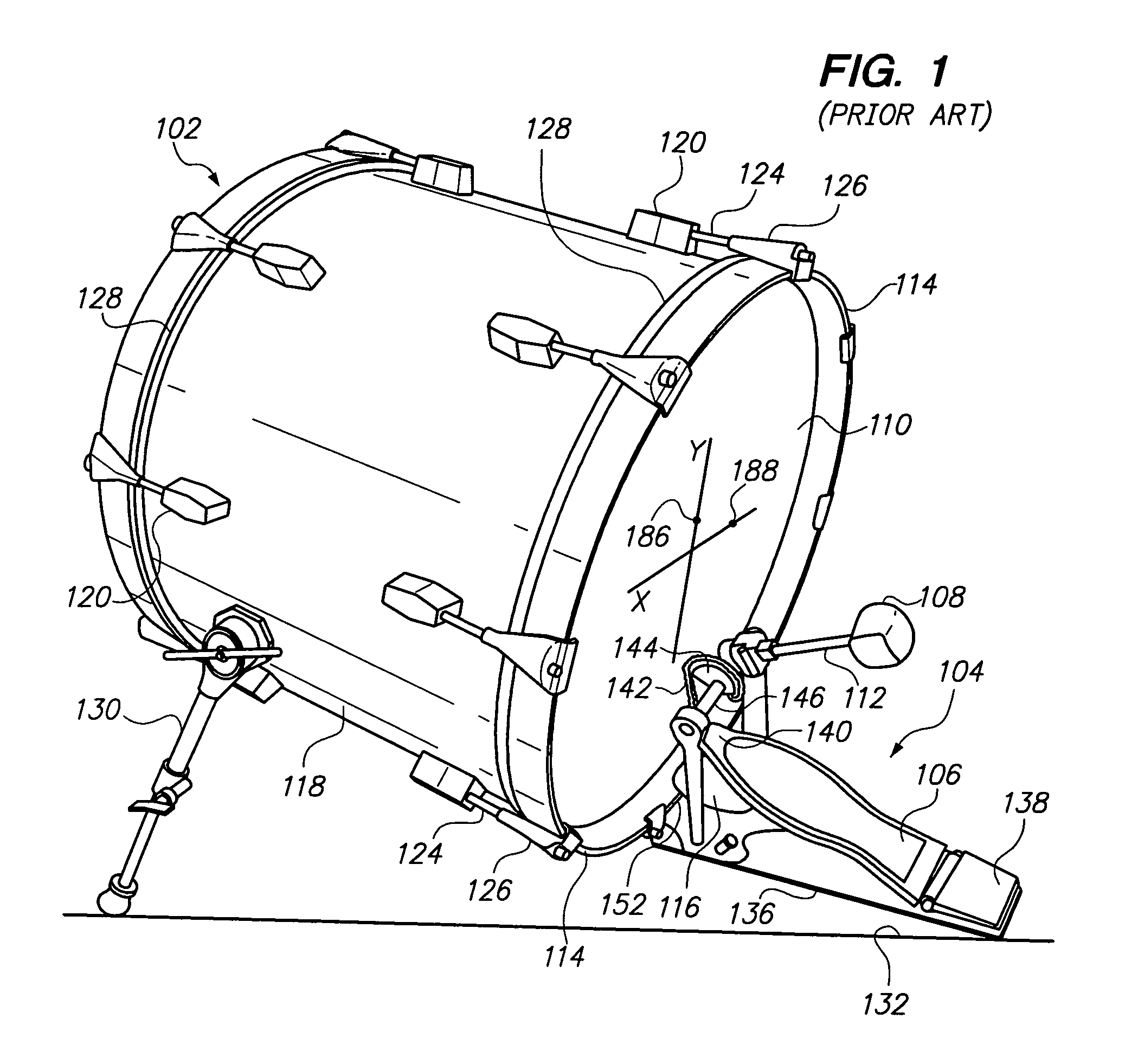
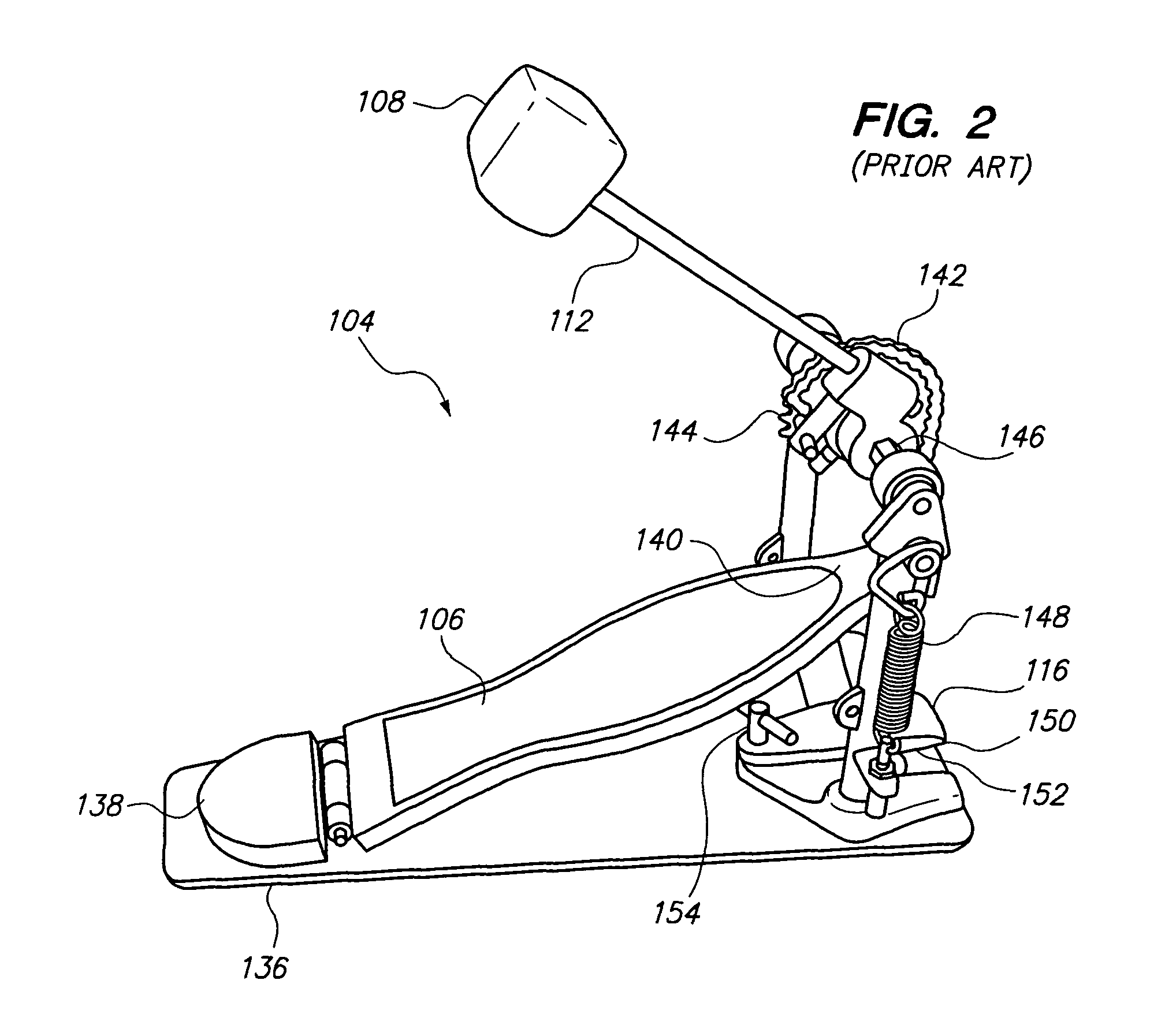
The present invention relates to a baseplate 100 for use with a bass drum 102 as shown in FIGS. 1-12. In particular, the baseplate 100 functions as a mechanical connection interface between a drum beater assembly 104 and the bass drum 102. The baseplate 100 provides alternative connection points for connecting the drum beater assembly 104 to the baseplate 100 where the drum beater assembly 104 includes a pedal board 106 and a beater head 108 as clearly shown in FIG. 2.

The alternative connection points provided by the baseplate 100 for the drum beater assembly 104 facilitates {a} the lateral adjustment of the beater head 108 of the drum beater assembly 104, {b} for adjusting the impact striking point of the beater head 108 onto a drum head 110 of the bass drum 102. This lateral adjustment of the impact striking point of the beater head 108 onto the drum head 110 is accomplished by using the baseplate 100 where {c} the length of a beater shaft 112 of the drum beater assembly 104, and ...


PUM


Abstract

A baseplate, for use with a bass drum, including a center plate and a pair of wings extending outwardly therefrom. Each wing cradles and is adjustably secured to a lug affixed to a drum shell of a bass drum. A connection plate unitarily constructed with and extending from the center plate includes a terminal end with a lip for adjustably interfacing with a pedal clamp of a drum beater assembly for connecting the drum beater assembly to the bass drum. The pedal clamp is removably connectable to any point along the lip for laterally adjusting the striking point of a beater head onto the bass drum, the bass drum isolated from the pedal clamp for improving the resonance performance thereof, without changing the length of a beater shaft or the feel of the drum beater assembly.

Description

BACKGROUND OF THE INVENTION1. Technical FieldThe present invention relates to a bass drum. More specifically, the present invention relates to methods and apparatus for a baseplate for use in connecting a drum beater assembly to the bass drum, where the baseplate provides alternative connection points for the drum beater assembly to laterally adjust the striking point of a beater head on the bass drum, where the length of a beater shaft and the distance from the striking point to the drum center are independently adjustable, where the bass drum is isolated from a pedal clamp for improving the resonance performance of the bass drum without changing the length of the beater shaft or the feel of the drum beater assembly.2. Background ArtModern drum sets typically include a bass drum and a drum beater assembly for providing a percussion sound background to accompany other instruments during a musical performance. In very general terms, a bass drum includes a cylindrical drum shell typic...

Claims


Application Information

Patent Timeline
IPC IPC(8): G10D13/04G10D13/02
CPCG10D13/00G10D13/006G10D13/023G10D13/11G10D13/16G10D13/02G10D13/28
Inventor BURNS, NICHOLAS R.
Owner BURNS NICHOLAS R
Why Eureka
Try Eureka