
3-way Doherty amplifier with minimum output network

a doherty amplifier and output network technology, which is applied in the direction of amplifiers, amplifier types, amplifiers with semiconductor devices/discharge tubes, etc., can solve the problems of increasing heavy saturation of the main stage, and significant degradation of the linearity between the input and output of the doherty amplifier, so as to achieve the effect of reducing the complexity reducing the cost of the input splitter, and increasing the efficiency of the 2-

Active Publication Date: 2011-09-20
AMPLEON NETHERLANDS
View PDF9 Cites 42 Cited by
  • Summary
  • Abstract
  • Description
  • Claims
  • Application Information

AI Technical Summary

Benefits of technology

[0005]The efficiency of a 2-way Doherty amplifier (having a main stage and a single peak stage) can be increased by extending it into a 3-way Doherty amplifier by adding a second peak stage. This will mainly benefit input signals with large peak-to-average ratios. A problem with this conventional 3-way Doherty amplifier is that the load-line modulation of the main stage stops at a certain power level, thereby causing heavy saturation of the main stage and, consequently, a significant degradation of the linearity between the input and output of the Doherty amplifier. A typical way of avoiding this degradation is using complicated drive profiles at the input, thereby increasing the complexity of the input splitter. Another problem is that, if the main and peak stages have equal configuration, marginal improvement is obtained relative to the symmetrical 2-way Doherty amplifier. This forces the designer to select different transistor sizes resulting in complicated device selection procedures.
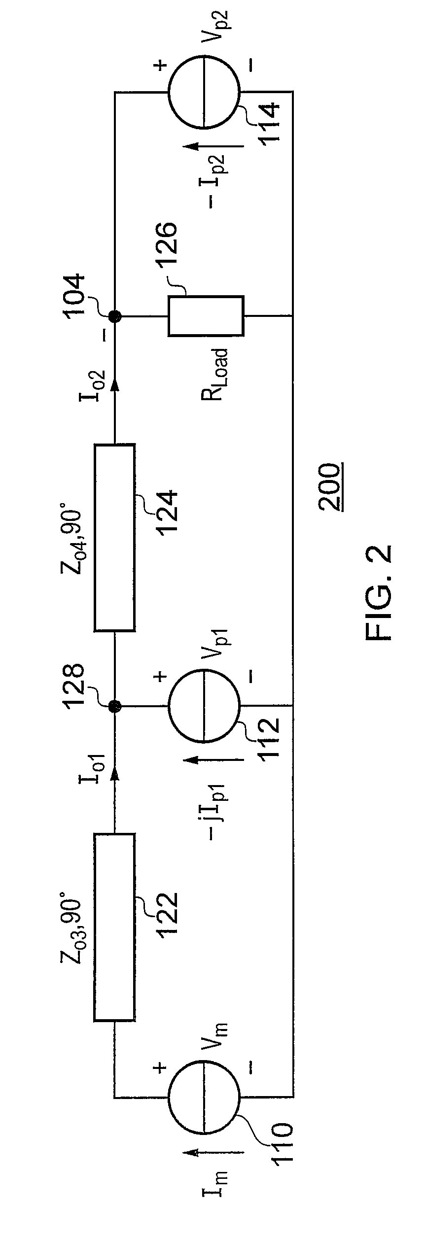
[0007]The inventors now consider the 4-port network to model a general output network of a 3-way Doherty amplifier. The output network is preferably configured in such a way that, as a whole, a real transformation (as opposed to a complex transformation having an imaginary part) is implemented between the outputs of the main stage and peak stages, on the one hand, and the output of the Doherty amplifier, on the other hand. The load of the Doherty amplifier is considered a resistance, i.e., a real-valued load. If the transformation had an imaginary part, the power efficiency would decrease. This then could be compensated for by adding compensation elements, but this in turn would contribute to the complexity and cost of the design. The inventors also aimed specifically at minimizing the number of components of the output network.
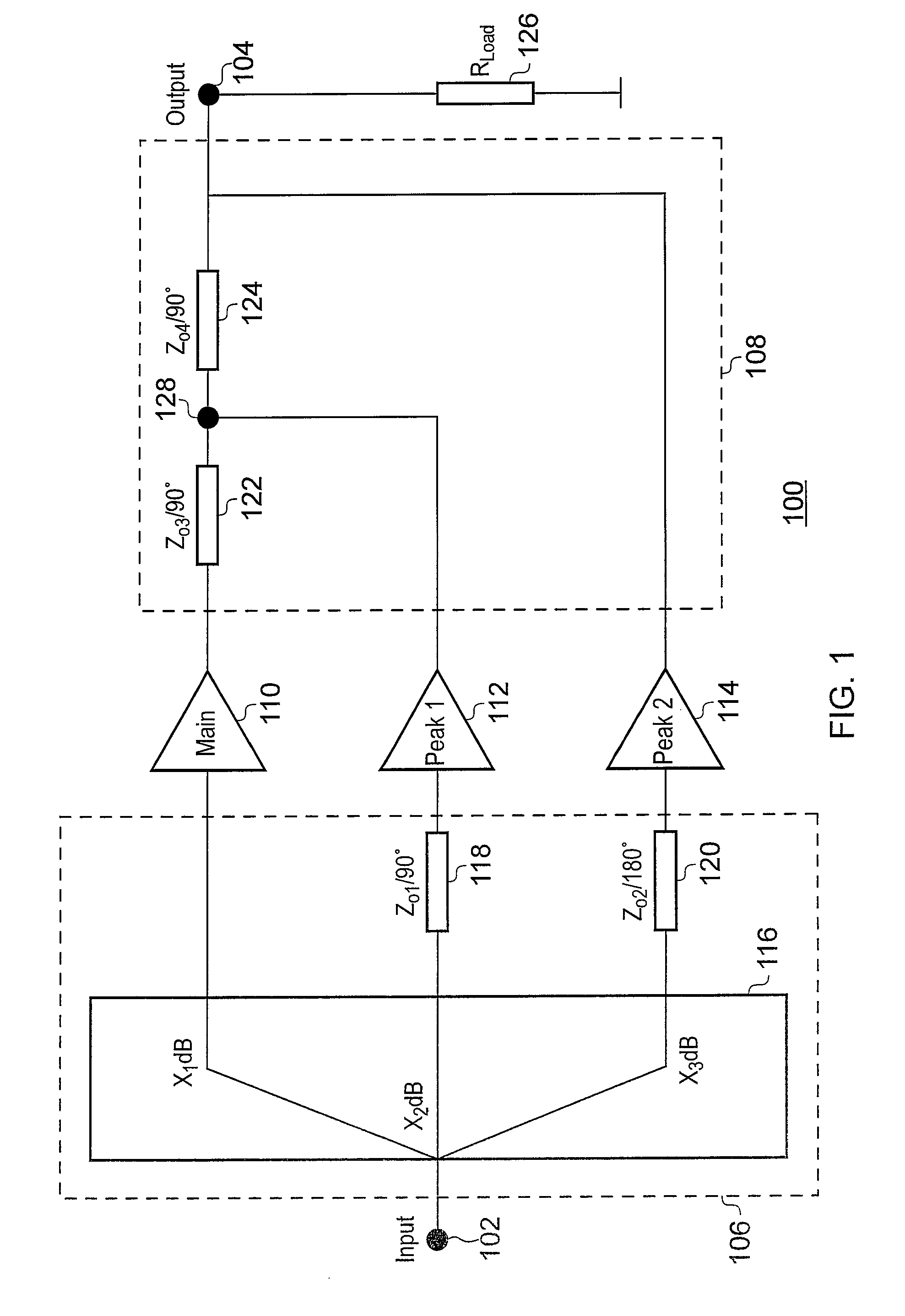
[0016]Thus, the invention provides a novel way of combining the outputs of main stage, first peak stage and second peak stage so as to enable load-line modulation over the full dynamic range and to avoid severe non-linear behavior. The novel way of combining accommodates the use of simple passive splitters. The novel way of combining provides for a high instantaneous efficiency at large back-offs with fewer than three device sizes. The novel way of combining enables a high instantaneous efficiency at 6 dB back-off and at 9.5 dB back-off with only a single device size.

Problems solved by technology

A problem with this conventional 3-way Doherty amplifier is that the load-line modulation of the main stage stops at a certain power level, thereby causing heavy saturation of the main stage and, consequently, a significant degradation of the linearity between the input and output of the Doherty amplifier.
A typical way of avoiding this degradation is using complicated drive profiles at the input, thereby increasing the complexity of the input splitter.
Another problem is that, if the main and peak stages have equal configuration, marginal improvement is obtained relative to the symmetrical 2-way Doherty amplifier.
This forces the designer to select different transistor sizes resulting in complicated device selection procedures.
This then could be compensated for by adding compensation elements, but this in turn would contribute to the complexity and cost of the design.

Method used


Image

  • 3-way Doherty amplifier with minimum output network
  • 3-way Doherty amplifier with minimum output network
  • 3-way Doherty amplifier with minimum output network

Examples


Embodiment Construction

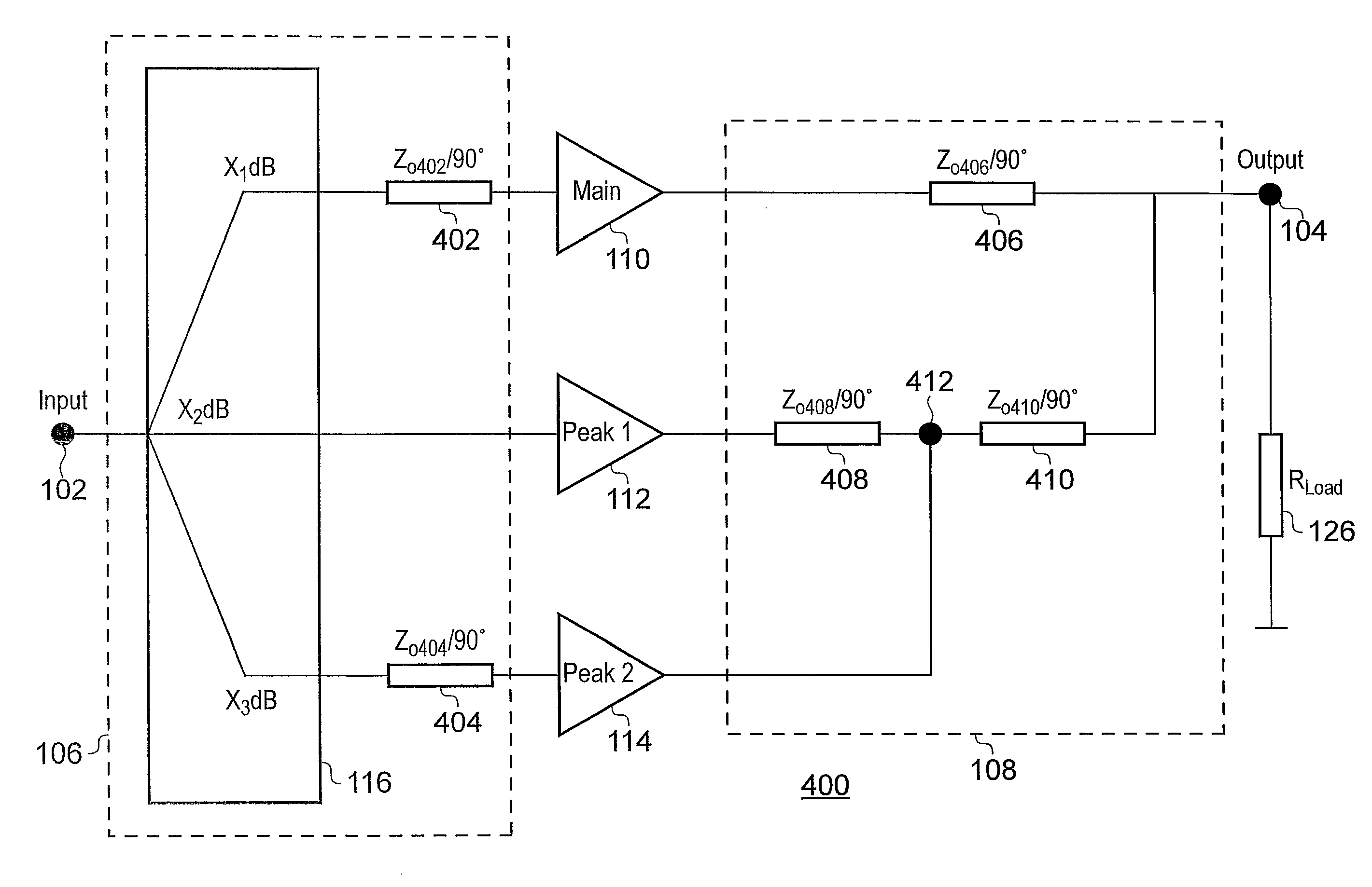
[0026]The efficiency of a 2-way Doherty amplifier can be increased by extending it with an additional peak stage so as to form a 3-way Doherty amplifier. One issue of the conventional 3-way Doherty amplifier is that the load-line modulation of the main stage stops at a certain power level, causing heavy saturation of the main stage and a severe degradation of the linearity. One way of avoiding this involves using complicated drive profiles at the input network of the 3-way Doherty amplifier, thereby increasing the complexity of the input splitter. Another issue is that if three equal transistor devices are used to implement the three stages, a marginal improvement is obtained with respect to the symmetrical 2-way Doherty amplifier. The designer is then forced to choose different transistor power sizes, resulting in complicated selection procedures for individual configurations of the 3-way Doherty amplifier. The invention now addresses both issues.

[0027]FIG. 1 is a diagram of a conv...


PUM


Abstract

A 3-way Doherty amplifier has an amplifier input and an amplifier output. The amplifier has a main stage, a first peak stage and a second peak stage. The amplifier has an input network connecting the amplifier input to the inputs of the stages, and an output network connecting the stages to the amplifier output. The output network implements a phase shift of 90° between the output of the main stage and the amplifier output; a phase shift of 180° between the output of the first peak stage and the amplifier output; and a phase shift of 90° between the third output and the amplifier output.

Description

FIELD OF THE INVENTION[0001]The invention relates to an electronic device comprising a 3-way Doherty amplifier with an amplifier input and an amplifier output, wherein the amplifier has a main stage, a first peak stage and a second peak device; the amplifier has an input network connecting the amplifier input to a first input of the main stage, to a second input of the first peak stage and to a third input of the second peak stage; and the amplifier has an output network connecting a first output of the main stage, a second output of the first peak stage and a third output of the second peak stage to the amplifier output.BACKGROUND OF THE INVENTION[0002]As known, a classical Doherty amplifier has two amplifying stages arranged in parallel and of the same power capability. The first one of the stages (main stage) operates in a class-AB amplifier mode and the second one (peak stage) operates in a class-C amplifier mode. These stages are separated at their inputs and at their outputs b...

Claims


Application Information

Patent Timeline
Patent Type & Authority Patents(United States)
IPC IPC(8): H03F3/68
CPCH03F1/0288H03F1/08H03F2200/391H03F2200/451H03F2200/543
Inventor GAJADHARSING, RADJINDREPERSADNEO, WENG CHUEN EDMUNDPELK, MARCO JOHANNESDE VREEDE, LEONARDUS CORNELIS NICOLAASZHAO, JI
Owner AMPLEON NETHERLANDS
Learn More