Method and apparatus for cause analysis involving configuration changes

a cause analysis and configuration change technology, applied in the field of causal analysis in computers, can solve problems such as user inability to easily fix the problem, and affect the application invocation,

Inactive Publication Date: 2011-09-20
HITACHI LTD
View PDF4 Cites 11 Cited by
  • Summary
  • Abstract
  • Description
  • Claims
  • Application Information

AI Technical Summary

Problems solved by technology

These configuration changes might affect the application invocation.
It does not seek to find the root cause, because even if the user knew the root cause, the user might not know how to fix it easily.

Method used


Image

  • Method and apparatus for cause analysis involving configuration changes
  • Method and apparatus for cause analysis involving configuration changes
  • Method and apparatus for cause analysis involving configuration changes

Examples


first embodiment

A. First Embodiment

1. System Configuration

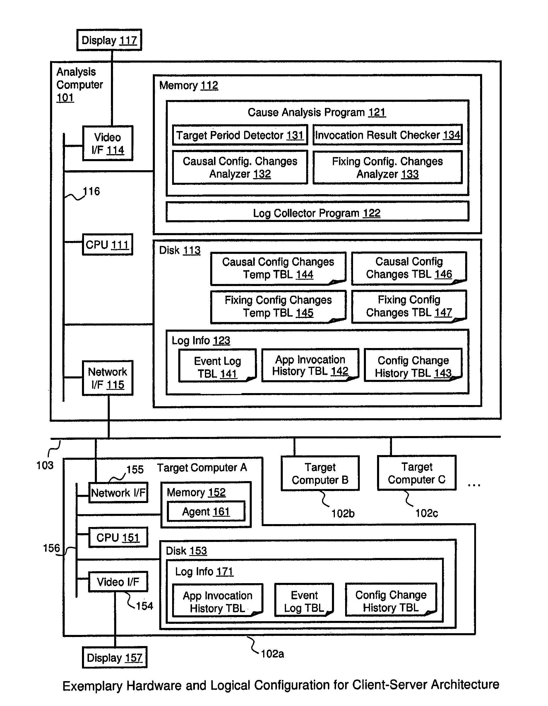
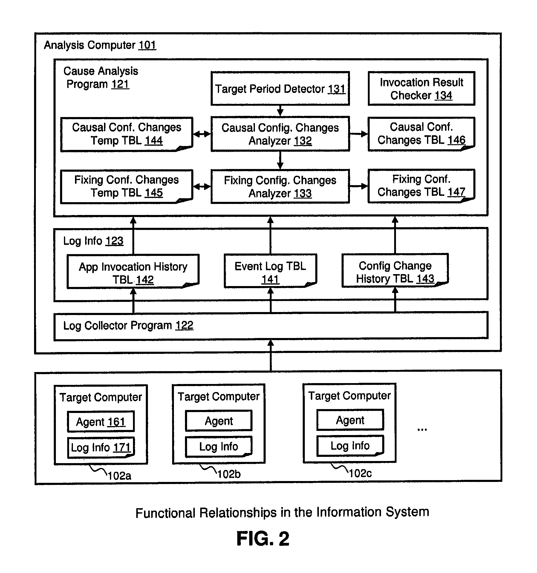
[0050]FIG. 1 illustrates an example of a hardware configuration for a client-server architecture in which the method and apparatus of the invention may be applied. An analysis computer 101 and a plurality of target computers 102 are connected through a LAN 103. The analysis computer 101 is a generic computer that includes a CPU 111, a memory 112, a disk 113, a video interface 114, and a network interface 115. Each element is connected through a system bus 116. The analysis computer 101 has a Cause Analysis Program 121 and a Log Collector Program 122 in its memory 112. The Cause Analysis Program 121 includes a Target Period Detector 131, a Causal Configuration Changes Analyzer 132, a Fixing Configuration Changes Analyzer 133, and an Invocation Result Checker 134, which are executed by the CPU 111. The analysis computer 101 has a Causal Configuration Changes Temporary Table 144, a Fixing Configuration Changes Temporary Table 145, a Causal Conf...

second embodiment

B. Second Embodiment

[0105]FIG. 21 shows an example of the Causal Configuration Changes Table 146-21 according to a second embodiment of the invention. In the second embodiment, the Cause Analysis Program 121 reuses and displays the result which was analyzed and stored in the past if the same analysis was done in the past. In order to do this, the Causal Configuration Changes Table 146 of FIG. 10 needs to be expanded. In FIG. 21, the columns from 1001 to 1005 are the same as those in FIG. 10. Additionally, new columns for Application Name 2101 and Analyzed Date Time 2102 are introduced. For example, the record 2111 shows that the analysis was done for the Application Name “DOC EDITOR” at the Analyzed Date Time “06 / 05 / 2008 14:20:12.” If the analysis condition is specified such that the Application Name is “DOC EDITOR” and the result of Target Period Detector 131 is the same, the Cause Analysis Program 121 can display the analysis result based on the Causal Configuration Changes Table ...

third embodiment

C. Third Embodiment

[0107]FIG. 23 shows an example of the Causal Configuration Changes Table 146-23 according to a third embodiment of the invention. In the third embodiment, the Cause Analysis Program 121 analyzes based on the combination of configuration changes. In order to do this, the Causal Configuration Changes Table 146 of FIG. 10 needs to be expanded. As seen in FIG. 23, the columns from 1001 to 1005 are the same as those in FIG. 10. Additionally, a new column for the Combination ID 2301 is introduced. There are records 2311-2317. For example, the record 2311 shows that the analysis was done by using all combinations of each configuration change. The same idea can be applied to expand the Fixing Configuration Change Table 147 of FIG. 12.

[0108]FIG. 24 is an example of a flow diagram illustrating the causal configuration change analysis process as executed by the Causal Configuration Changes Analyzer 132 according to the third embodiment of the invention. Step 1701, 1702 and 1...


PUM


Abstract

A technique determines which configuration change(s) caused an application invocation failure of a computer application without the need for a knowledge database. To determine which configuration change is the most likely cause, the cause analysis program (121) checks other computers (102) that have experienced the same configuration changes. The cause analysis program checks and counts the application invocation results before and after each configuration change is done. If the same configuration changes are found in the other computers, the program checks whether each configuration change caused or cured the same problem in that computer. The program counts the similar cases for all of the computers. Subsequently, the program calculates the ratio of those instances involving a change from success to failure and the ratio of those instances involving a change from failure to success out of all instances for each configuration change.

Description

BACKGROUND OF THE INVENTION[0001]The present invention relates generally to causal analysis in computers and, more particularly, cause analysis involving configuration changes for finding a solution to an application failure by analyzing configuration changes without using a knowledge database.[0002]One of the most stressful jobs for administrators of the desktop computing environment is the cause analysis in the case where trouble occurs (trouble shooting). The causal analysis is also critical for the helpdesk person who needs to provide the solution to the caller. End users tend to install many kinds of software or change OS settings that might cause the problems. Furthermore, because a number of automatic upgrade programs routinely run in the end user computer, the configuration of the computer can be changed without the end user's awareness. Thus, the end user does not know when the configuration became faulty and may not remember when the problem began. Administrators or helpde...

Claims


Application Information

Patent Timeline
Patent Type & Authority Patents(United States)
IPC IPC(8): G06F11/00
CPCG06F11/079H04L41/0813H04L41/0856H04L41/0866G06F11/0706G06F11/0751H04L41/0681
Inventor KUDO, YUTAKAMASUISHI, TETSUYAFUJITA, TAKAHIROONO, YOSHITSUGU
Owner HITACHI LTD
Why Eureka
Try Eureka