Standing-seam roof assembly bracket

a technology of assembly brackets and standing seams, which is applied in the direction of ceilings, doors/windows, building repairs, etc., can solve the problems of insufficient connection, and achieve the effect of convenient connection, wide width and strength, and strong and proper connection to the structur

Active Publication Date: 2011-09-27
ROOF HUGGER LLC
View PDF18 Cites 27 Cited by
  • Summary
  • Abstract
  • Description
  • Claims
  • Application Information

AI Technical Summary

Benefits of technology

[0008]In an exemplary embodiment, the invention includes a bracket with configured cut-outs in the lower flange and web section that nest in close proximity to the existing standing seam roof so that a strong and proper connection to the structure can be readily achieved. The vertical web may vary in height to accommodate additional insulation, utilities or other accessories in the space between the two panels. The upper flange has ample width and strength to receive various means of attachment of the new roof panels. The bracket also includes pre-punched holes in the lower flange to properly pre-locate fasteners and prevent the lower flange from riding up on the fastener shank during installation which can result in an inadequate connection.
[0009]The bracket also includes an anti-roll tab adjacent the cut-outs which are attached to the existing roof panel. The anti-roll tabs can be bent in the field to contact the existing roof panel, providing a versatile, adaptable and stable bracket readily configured to the many variations of panel profiles now existing in the field. The bracket can be installed over panels the have a compressible substrate beneath them. The invention, therefore, provides a flexible, stable bracket shaped to absorb distortion forces of thermal expansion and contraction of the panels and their loads resulting from wind forces or seismic disturbance, while also providing a structurally correct attachment surface for the new roof and / or wall panels

Problems solved by technology

The bracket also includes pre-punched holes in the lower flange to properly pre-locate fasteners and prevent the lower flange from riding up on the fastener shank during installation which can result in an inadequate connection.

Method used


Image

  • Standing-seam roof assembly bracket
  • Standing-seam roof assembly bracket
  • Standing-seam roof assembly bracket

Examples


Embodiment Construction

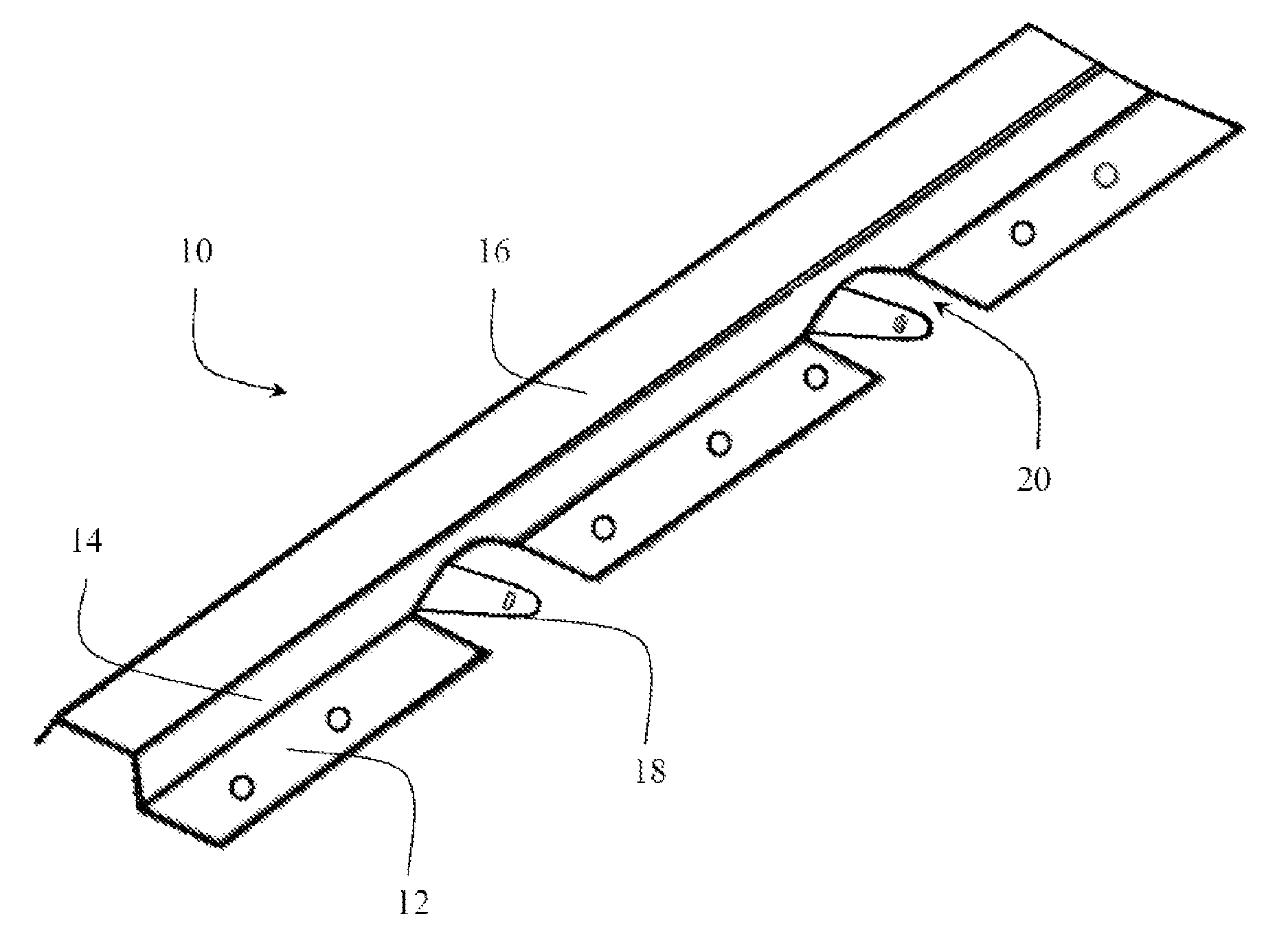
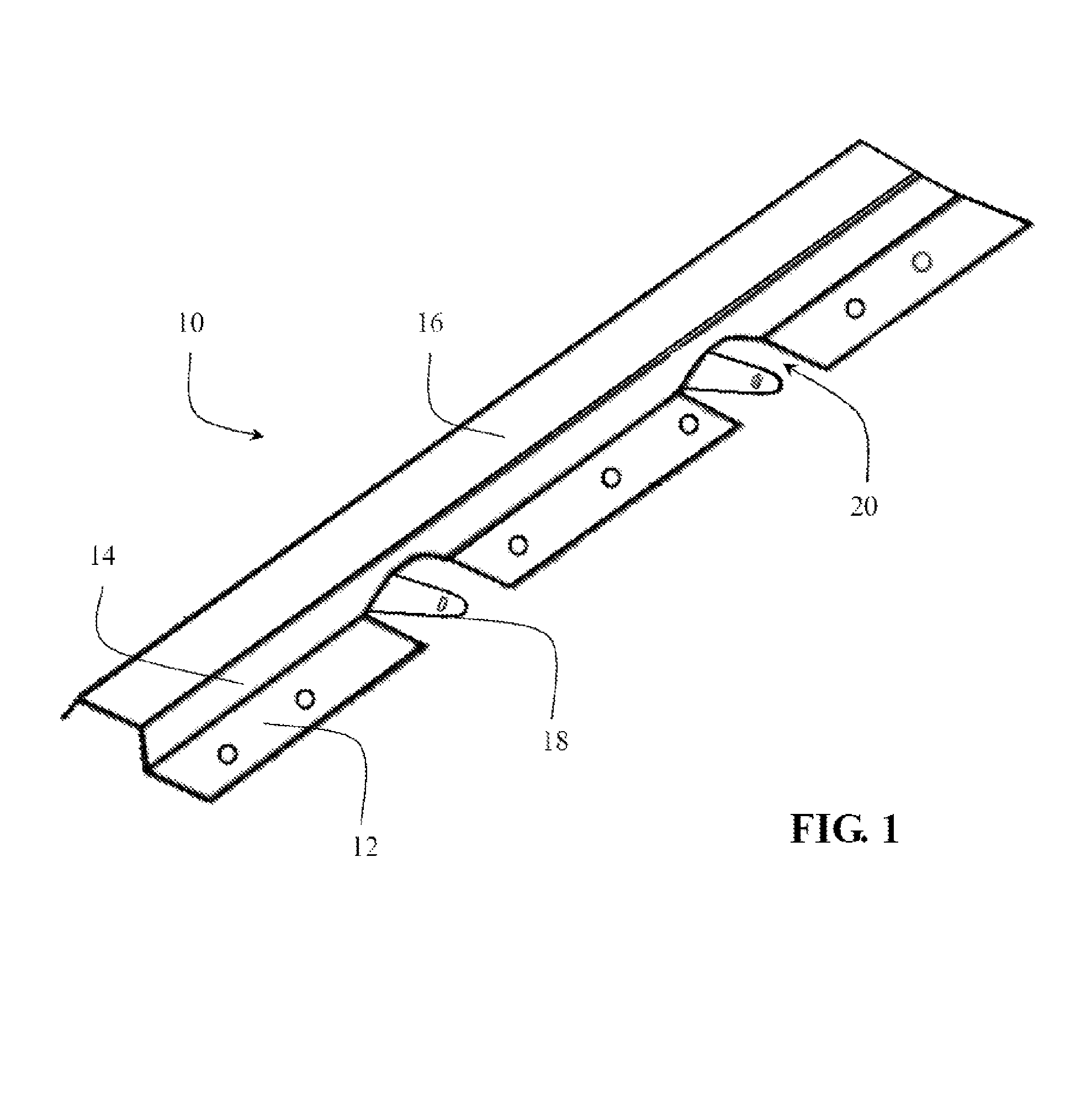
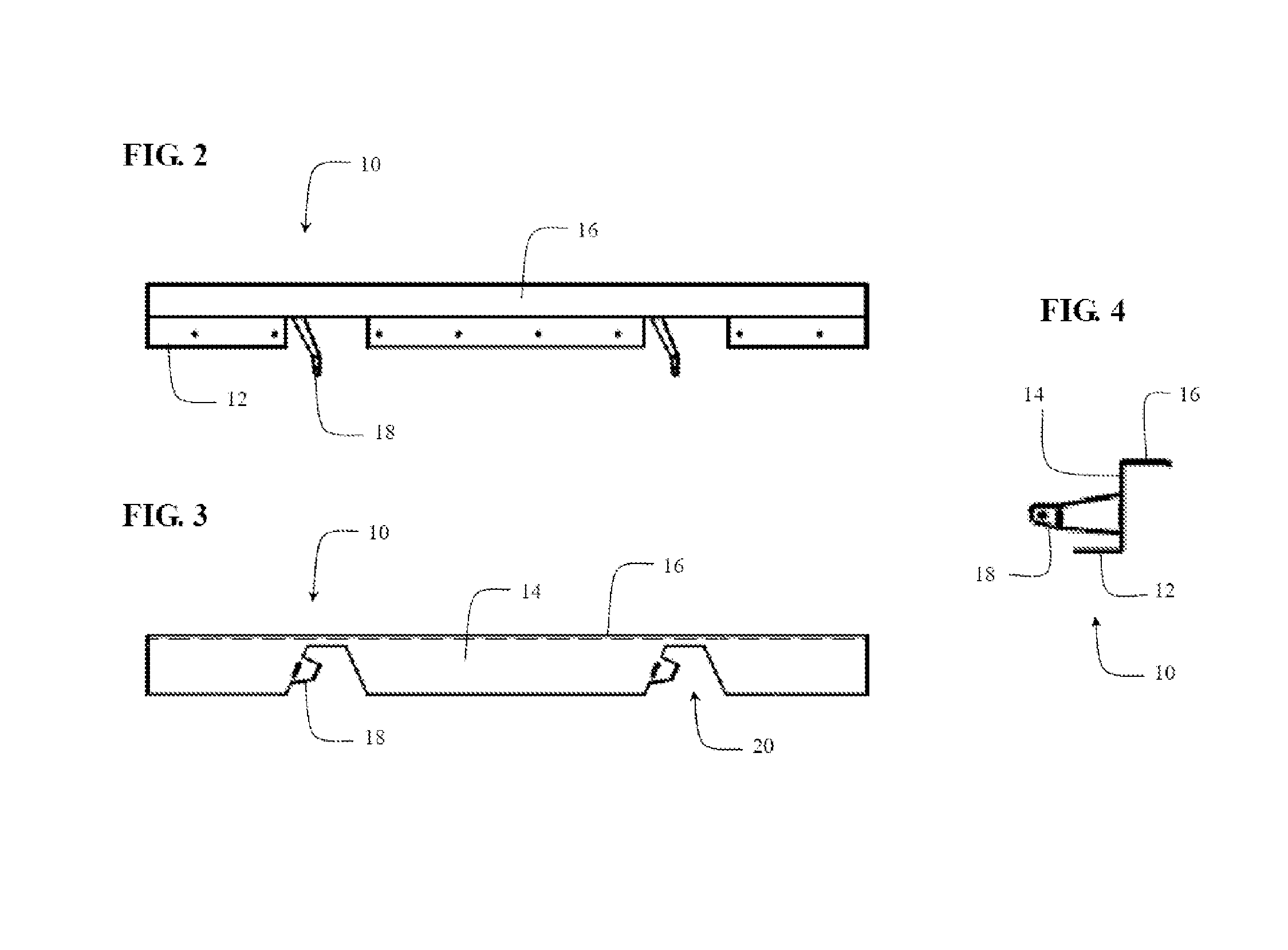
[0022]Shown in FIGS. 1-5B, the invention includes bracket 10 for re-roofing a standing seam roof, otherwise known as a sub-purlin, having an anti-roll bracing arm. The bracket of one embodiment attaches to the existing high clip metal standing seam roof panel. It is contemplated that the bracket 10 can be fabricated from nearly any material from which building panels are fabricated. Such materials are easily fabricated into one of any number of shapes and sizes, depending on the particular system requirements.

[0023]In one embodiment, the bracket is substantially Z-shaped. The bracket of this embodiment includes generally vertical web 14 between a lower 12 and upper flanges 16. Web 12 has a number of cut-outs 20 along its length which receive the contour of the existing roof panels. Anti-roll arm 18, positioned adjacent cut-outs 20, is then pressed into contact with and fastened to the existing roof panel. Anti-roll arm 18 prevents the bracket and new roof from lateral movement with ...


PUM


Abstract

A bracket for use in retro-fitting metal clad buildings to facilitate attachment of new roof or wall panels of any desired profile, directly over existing ribbed or fluted panels of various configurations. Commonly known in the trades as a sub purlin or sub girt. Generally a one piece Z shaped metal bracket with a substantially vertical web between opposed top and bottom flanges in a parallel plane. The bottom flange and adjacent lower portion of the web contain a series of notches that allow the bracket to nest onto and over existing ribbed roof or wall panels. The top flange is automatically in position, lying flat and continuous, to receive and attach the new panels thereto. An ant-roll tab further connects the web to the existing roof panel. The solid portion of lower flange is preferred to be positioned directly above the underlying substructural support system members of the existing building to assure a structurally sound attachment of bracket to the building. Pre-punched holes in the solid portion of lower flange dictate required location, number and size of fasteners to be inserted through lower rib surface of existing panel into substructural system members.

Description

CROSS-REFERENCE TO RELATED APPLICATIONS[0001]This application is a nonprovisional application of U.S. provisional patent application Ser. No. 60 / 948,295, filed Jul. 6, 2008.FIELD OF INVENTION[0002]The present invention relates generally to metal building structures: Specifically to the retro-fitting of new roof and / or wall panels over existing ribbed, fluted, profiled or standing seam roof and / or wall panels.BACKGROUND OF THE INVENTION[0003]A metal building, generally, is a lightweight structure consisting of vertical steel columns, steel rafter beams bolted to the vertical columns and generally spaced from 20 to 30 feet apart. The rafter beams are generally sloped to provide positive drainage. Spanning the columns and rafter beams at sidewalls and roof are a series of light gauge sub-structural “z” or “c” sections bolted to the columns and rafter beams. These are generally on 4′ to 5′ spacing and run perpendicular to the columns and rafter beams, commonly known in the trade as purl...

Claims


Application Information

Patent Timeline
Patent Type & Authority Patents(United States)
IPC IPC(8): E04B1/00
CPCE04D13/165E04D3/3608
Inventor NELSON, DALE G.MCCONNOHIE, DUANE V.
Owner ROOF HUGGER LLC
Why Eureka
Try Eureka