
Articulating interbody spacer, vertebral body replacement

a technology of interbody which is applied in the field of medical devices, can solve the problems of limiting the range of motion of vertebral spacers and interbody devices, and causing the inability to provide adequate surface coverage and ease of ideal positioning, etc., and limiting the range of motion. , to achieve the effect of reducing the risk of injury

Inactive Publication Date: 2011-09-27
CUSTOM SPINE INC
View PDF15 Cites 208 Cited by
  • Summary
  • Abstract
  • Description
  • Claims
  • Application Information

AI Technical Summary

Benefits of technology

The assembly facilitates easier insertion and optimal surface coverage within the vertebral body, reducing the risk of subsidence and improving surgical efficiency by allowing for precise placement and stability during spinal fusion procedures.

Problems solved by technology

While, the spine is capable of multiple degrees of motion, spinal injuries or anatomical irregularities may result in spinal pathologies which limit this range of motion.
Most conventional vertebral spacers and inter body devices do not provide adequate surface coverage and ease of ideal positioning, and others are generally too large or bulky to be inserted in the traditional posterior or transforaminal lumbar interbody approaches.
Generally, the conventional designs do not provide the surface coverage and ideal placement located towards the anterior side of the vertebral endplate while being implanted through a narrow passageway for transforaminal lumbar interbody fusion (TLIF) or posterior lumbar interbody fusion (PLIF) approaches.
Due to nerve anatomy, this can be a difficult task even for skilled surgeons.

Method used


Image

  • Articulating interbody spacer, vertebral body replacement
  • Articulating interbody spacer, vertebral body replacement
  • Articulating interbody spacer, vertebral body replacement

Examples


Embodiment Construction

[0035]The embodiments herein and the various features and advantageous details thereof are explained more fully with reference to the non-limiting embodiments that are illustrated in the accompanying drawings and detailed in the following description. Descriptions of well-known components and processing techniques are omitted so as to not unnecessarily obscure the embodiments herein. The examples used herein are intended merely to facilitate an understanding of ways in which the embodiments herein may be practiced and to further enable those of skill in the art to practice the embodiments herein. Accordingly, the examples should not be construed as limiting the scope of the embodiments herein.

[0036]As mentioned, there remains a need for a new spinal spacer capable of being properly inserted towards the anterior side of the vertebral endplate and which can be easily constructed and ultimately used by a surgeon during a spinal surgical procedure. The embodiments herein achieve this by...


PUM


Abstract

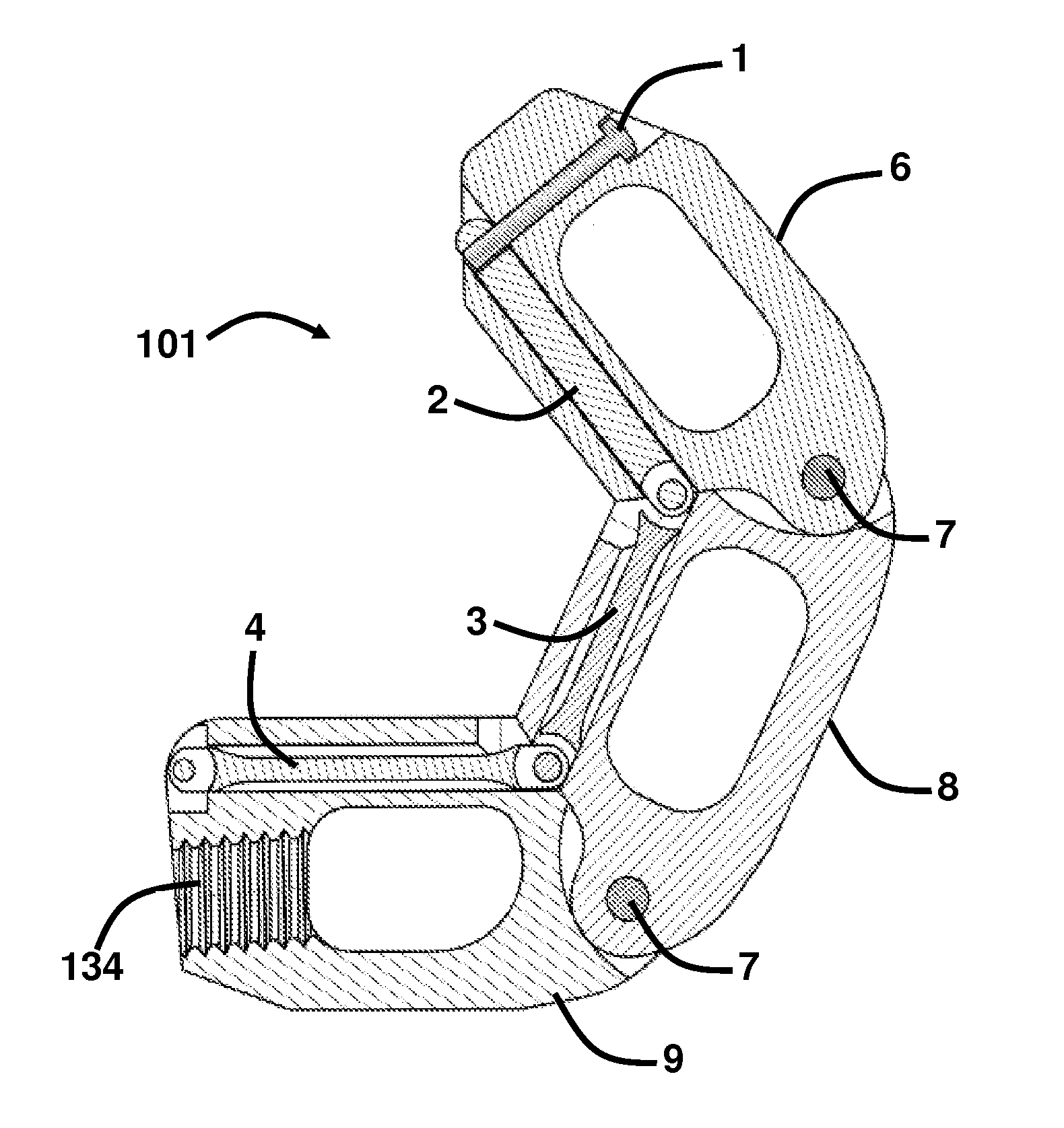
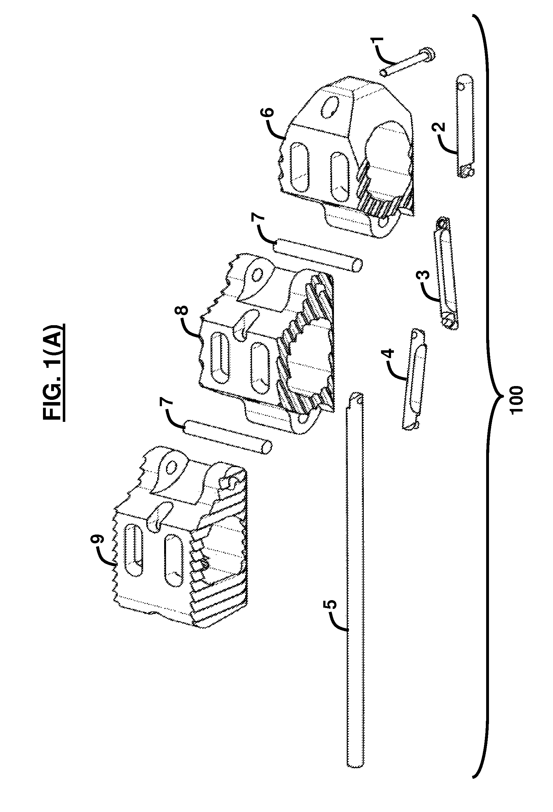
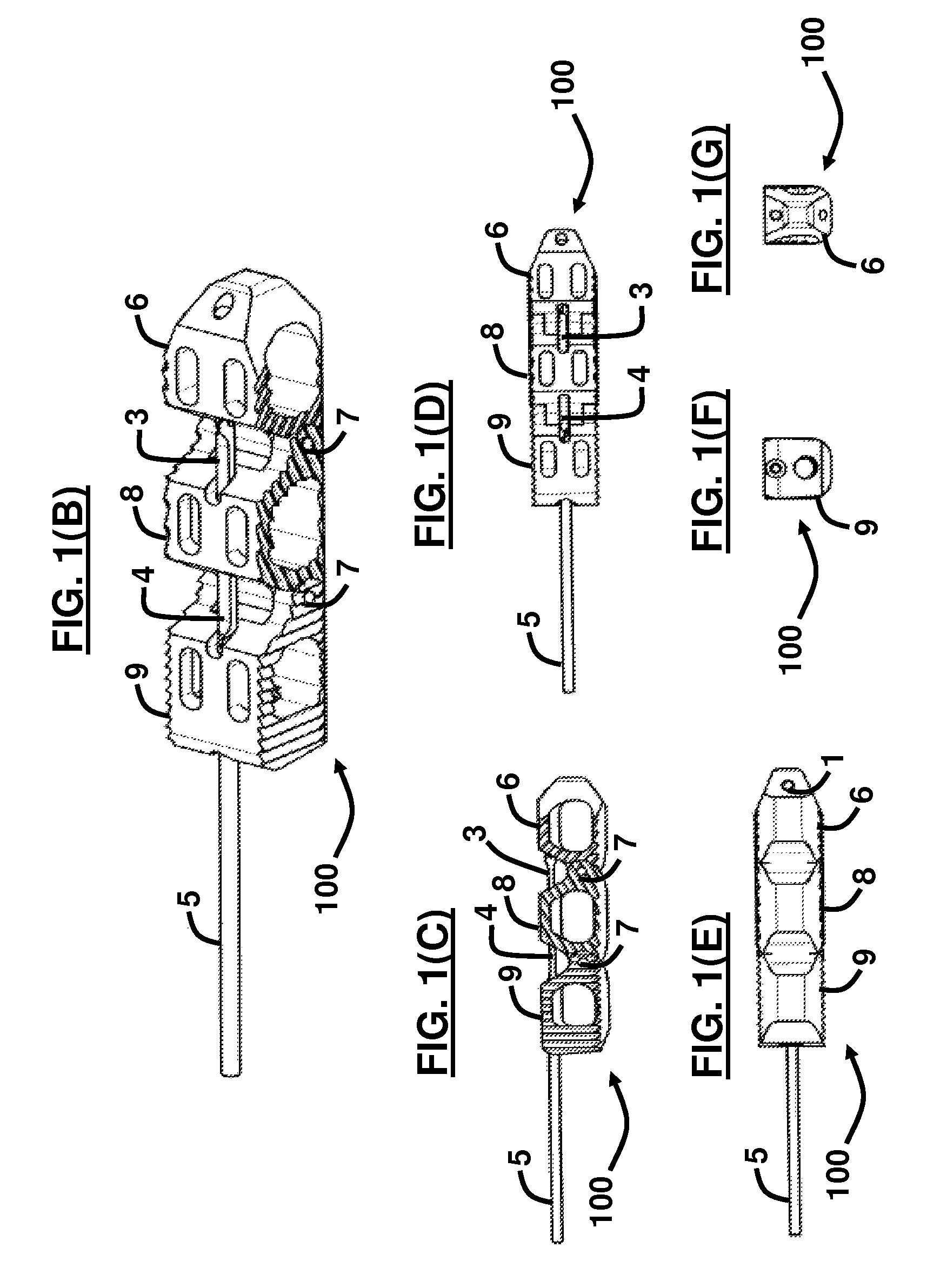
An interbody spacer implant assembly for interbody fusion in a vertebral body and a method of insertion comprises a plurality of links and an elongated connector mechanism adapted to retain the plurality of links and allow the plurality of links to articulate with respect to one another. An interbody spacer implant apparatus for interbody fusion in a vertebral body comprises a plurality of individually articulating links and a connector mechanism adapted to retain the plurality of links and allow the plurality of links to articulate with respect to one another, wherein the connector mechanism is dimensioned and configured to have a length-to-width ratio greater than a length-to-width ratio of each of the plurality of links. The apparatus may further comprise an insertion rod adapted to insert the plurality of links and the connector mechanism into the vertebral body.

Description

BACKGROUND[0001]1. Technical Field[0002]The embodiments herein generally relate to medical devices, and, more particularly, to implantable devices used to stabilize the human spine.[0003]2. Description of the Related Art[0004]The spinal column is a highly flexible structure comprising bones and connective tissue. While, the spine is capable of multiple degrees of motion, spinal injuries or anatomical irregularities may result in spinal pathologies which limit this range of motion. Orthopedic surgeons often aim to correct spinal irregularities and restore stability to traumatized through immobilization of spinal components.[0005]Most conventional vertebral spacers and inter body devices do not provide adequate surface coverage and ease of ideal positioning, and others are generally too large or bulky to be inserted in the traditional posterior or transforaminal lumbar interbody approaches. The conventional large-sized spacers that may provide this adequate surface coverage typically ...

Claims


Application Information

Patent Timeline
Patent Type & Authority Patents(United States)
IPC IPC(8): A61F2/44
CPCA61F2/4455A61F2/4611A61F2/30965A61F2002/30133A61F2002/30354A61F2002/30462A61F2002/30471A61F2002/30538A61F2002/30579A61F2002/30892A61F2002/4415A61F2002/4475A61F2002/448A61F2002/4629A61F2220/0033A61F2220/0075A61F2220/0091A61F2230/0015A61F2250/0006A61F2310/00017A61F2310/00023A61F2002/30593A61F2/4425A61F2/447
Inventor MCCLELLAN, III, JOHN W.ABDELGANY, MAHMOUD F.
Owner CUSTOM SPINE INC
Learn More