Manufacturing method of plastic lens and the lens

a manufacturing method and lens technology, applied in the field of plastic lens and lens manufacturing, can solve the problems of lens striae and polarization irregularities are generated, and the lens lacks uniformity when the lens is dyed, and the mechanical strength is not respected

Inactive Publication Date: 2011-09-27
FOREVER VISION
View PDF9 Cites 0 Cited by
  • Summary
  • Abstract
  • Description
  • Claims
  • Application Information

AI Technical Summary

Benefits of technology

[0007]The fourth aspect of the present invention is characterized in that an engaging member for engaging the mold is provided movably in the vertical direction close to the opening portion of the cylinder so as to incline a posture of the upper mold to be arranged and to lower the upper mold in a posture having an angle with respect to the mold which is arranged below, whereby the upper mold is arranged on the placed resin molten material in a state that air is not entangled. It is preferable to incorporate the engaging member into a guide pole which performs the positioning of the mold in the opening portion. Since four guide poles are provided, four sets of engaging members are also arranged. Since the respective molds which are arranged at the lower side and the upper side are transported from the heating furnace in an overlapped manner as mentioned above, first of all, the lower mold is moved onto the four sets of engaging members using the mold transport device, four sets of engaging members are lowered at a same speed, the mold is moved to the opening portion of the cylinder and is placed on a piston described later and, thereafter, the engaging members return to original positions. Next, the resin molten material is placed on the lower mold and, thereafter, the upper mold is again moved onto the engaging member. Two sets of engaging members are lowered and, subsequently, another two sets of engaging members are lowered so as to incline the upper mold. Thereafter, all engaging members are lowered and hence, the mold which is held in the inclined posture can be placed on the resin molten material. The mold which is lowered from above the resin molten material in the inclined posture the mold is initially brought into point or line contact with the resin molten material and the portions thereof which come into contact with the resin molten material are gradually enlarged whereby the entanglement of air can be prevented.
[0008]The fifth aspect of the present invention is characterized in that out of a step of heating the mold, a step of arranging the mold on the cylinder, a forming step of moving two molds including a resin molten material close to each other thus pushing the resin molten material, an annealing step of integrally heating the mold and formed resin molten material after pressing, and a step of taking out the lens from the mold, the plastic lens is manufactured by making at least one step independently from other steps. By manipulating these steps independently, the forming accuracy is enhanced and hence, even when any trouble occurs in each step, it is unnecessary to retract the work whereby the stability of manufacturing can be ensured. Particularly, by performing the annealing step in batch processing, it is possible to accurately control periods for a high temperature portion and a gradual cooling portion of the furnace inner temperature and hence, the lens having the small internal strain can be easily obtained. Although the above-mentioned steps may be incorporated into the manufacturing line as a series of steps, since the required periods for respective steps are naturally different from each other, when the time-oriented restriction is imparted to the forming step, the time for pressing the resin molten material is shortened thus giving rise to the generation of strains in the inside of the lens.
[0009]According to the present invention, the mass production of the plastic lens having the extremely small optical strain using the optical thermoplastic resin is facilitated. As the thermoplastic resin, for example, polycarbonate resin or the like is preferably used. Since the method of the present invention can use the resin having the large molecular weight compared to the injection molding, the plastic lens exhibits the high mechanical strength. Further, the plastic lens produced by the forming method of the present invention has no internal strain and hence, chipping or cracks are not generated during a boring operation. Since the orientation of resin in the inside of the lens is extremely small, when the lens is dyed, the die irregularities are not generated. By providing the engaging members to the guide poles thus enabling the accurate movement of the molds, the accuracy of the forming steps can be remarkably enhanced and, at the same time, by supplying a larger amount of resin molten material to the center portion than other portions, it is possible to extend the resin uniformly at the time of molding thus preventing the generation of the agitation flow of resin.
[0010]In the plastic lens which is obtained by the above-mentioned manufacturing method, the resin molten material is substantially uniformly extended toward the periphery from the center of the mold and hence, it is possible to obtain the optically uniform lens with respect to the striae, the polarization and the like. Particularly, the molten resin is uniformly extended with respect to a lens which changes a curvature of a forming surface thereof such as an increment multifocal lens, an aspherical lens or the like and hence, the accurate formed surface is obtained whereby it is possible to provide the lens with the least strain. Particularly, although polycarbonate resin is liable to generate birefringence, the lens manufactured by the present invention is an excellent plastic lens in which an agitation flow of resin is not recognized even when the lens is observed through a polarization filter.

Problems solved by technology

Accordingly, turbulence is liable to be easily generated in the flow of resin in the inside of the mold and hence, there observed is a tendency that striae and polarization irregularities are generated in a produced lens and, at the same time, there also observed is a tendency that the lens lacks uniformity when the lens is dyed.
Although resin having a relatively small molecular weight is used to improve the resin flow, there exist irregularities with respect to the mechanical strength and hence, an utmost care is required for forming holes.
However, since the lens is integrally manufactured at a high speed, facilities are liable to become excessive to take a time-sequential balance among respective steps and, at the same time, there exist portions to be improved in respective steps.
Further, the resin molten material has the columnar shape and has a fixed thickness and hence, when the resin molten material is pressed and elongated using the mold, the spreading of resin is not always generated such that the resin spreads uniformly outwardly from the center.

Method used


Image

  • Manufacturing method of plastic lens and the lens
  • Manufacturing method of plastic lens and the lens
  • Manufacturing method of plastic lens and the lens

Examples


embodiment 1

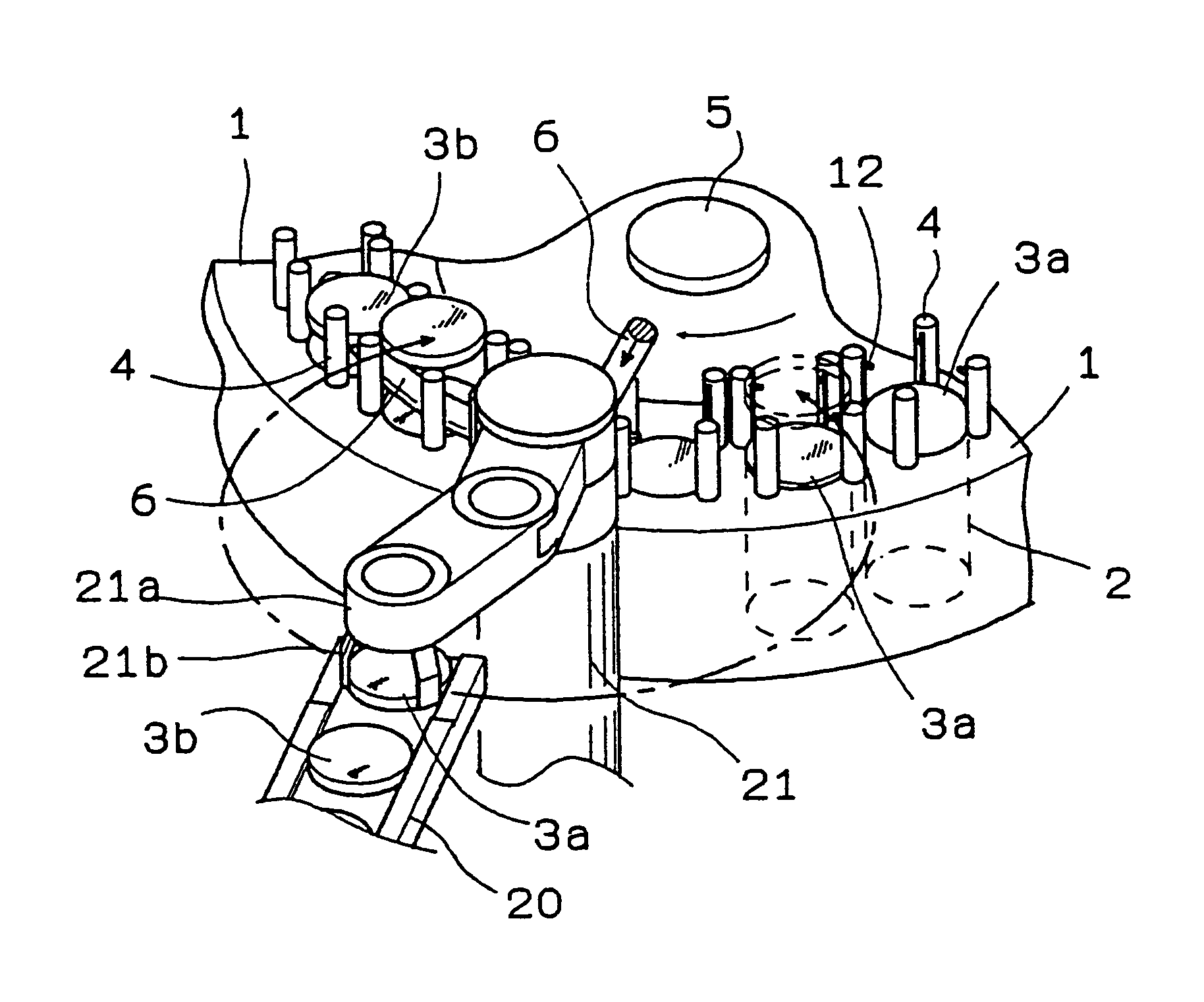
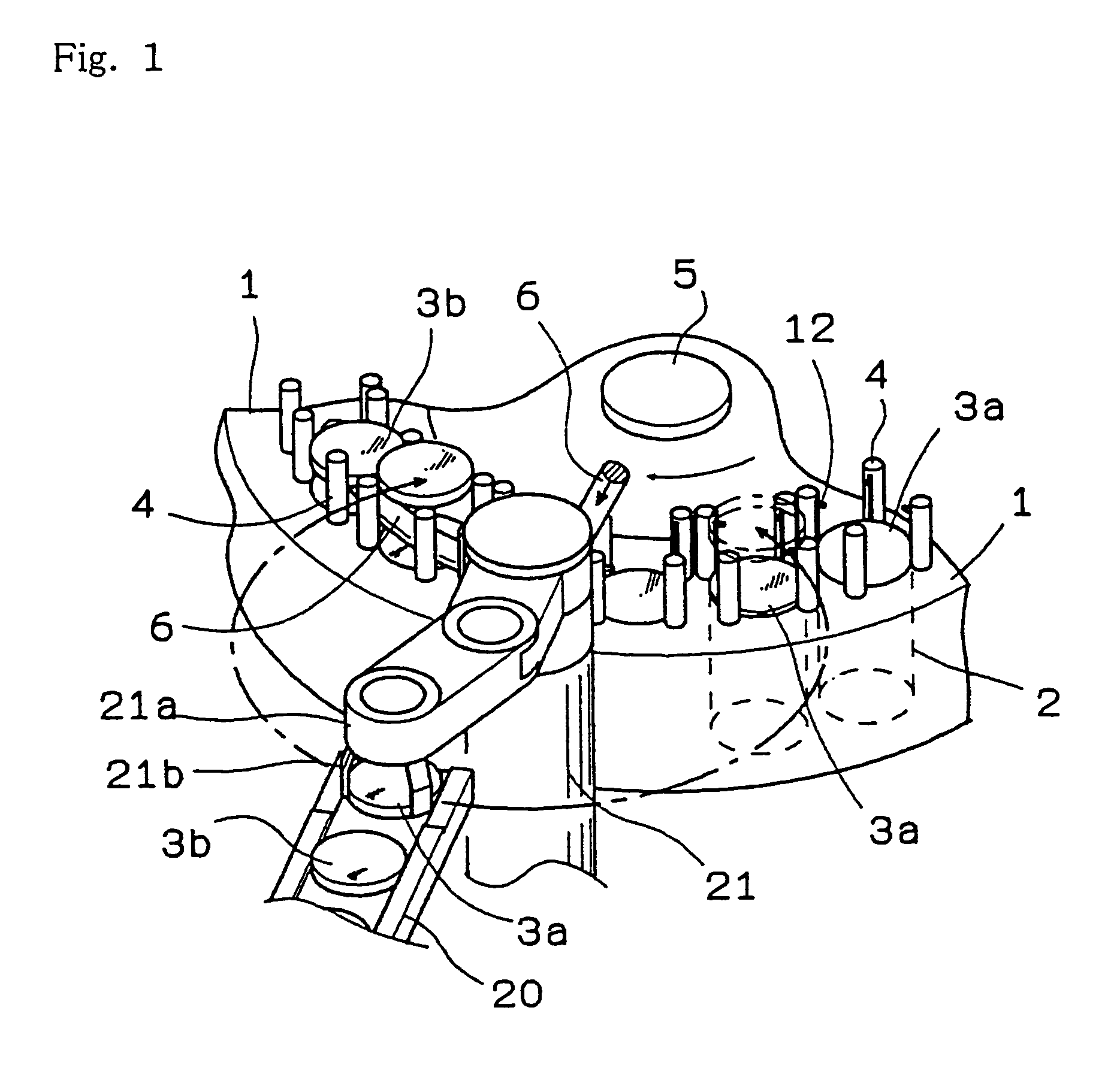
[0018]FIG. 1 is a perspective view schematically showing a portion of a turntable 1. The turntable 1, as a whole, has a circular disc shape and respective members which are shown in a perspective view are arranged on all periphery of the turntable 1. The turntable 1 is rotated about a rotary shaft 5 at a fixed speed. With respect to respective molds which are arranged at a lower side and an upper side, a pair of molds having a planned combination are arranged in the fore-and-aft direction or in the left-and-right direction, and is placed on a transport platform 20 of a heating furnace to be heated. In this embodiment, the transport platform 20 is moved in the heating furnace, wherein the pair of molds are arranged in the fore-and-aft direction at an exit, that is, the mold 3a which is arranged at the lower side and the mold 3b which is arranged at the upper side are arranged in series in the advancing direction. Transporting of the mold is performed by one transport means. In arrang...

embodiment 2

[0020]When the nozzle of the extruding machine has a circular shape and the resin molten material which is discharged from the nozzle is discharged at a fixed flow speed, provided that a moving amount of the lower mold is fixed, a thickness of the resin molten material placed on the lower mold is fixed. Here, a moving speed of the lower mold is larger than a discharge speed or a fall speed of the resin molten material, the resin molten material is elongated and the thickness thereof is decreased, while when the moving speed of the lower mold is smaller than the discharge speed or the fall speed of the resin molten material, the resin molten material is liable to dwell and hence, the thickness of the resin molten material is increased. Further, when an opening diameter of the nozzle is increased, the diameter of the resin molten material is increased, while when the opening diameter of the nozzle is decreased, the diameter of the resin molten material is decreased. Still furthermore,...

embodiment 3

[0022]Although the upper mold 3b is arranged on the resin molten material while being guided by the guide poles 4, it is preferable to bring the upper mold 3b in contact with the resin molten material in an inclined posture with respect to the resin molten material. First of all, the mold is allowed to fall such that a one-side end portion of the mold is brought into contact with the resin molten material and the mold is sequentially shifted to a horizontal posture thus preventing the entanglement of air. As shown in FIG. 5A, each guide pole 4 is positioned on the extension line of the wall surface of the cylinder 2 on the turntable 1 and performs the positioning of the mold. Since the guide poles 4 are provided at four positions around the cylinder 2, the mold is temporarily held at a height which prevents the mold from coming into contact with the resin molten material by providing the engaging members 12 in the inside of the guide poles 4. The guide pole 4 is constituted of a tub...


PUM

PropertyMeasurementUnit
melting pointaaaaaaaaaa
glass transition point Tgaaaaaaaaaa
temperatureaaaaaaaaaa

Abstract

The present invention provides a plastic lens which can simplify the installation, can enhance the forming accuracy and can exhibit extremely small optical irregularities. Molds having a planned combination are heated, using at least one pre-numerically controlled automatic chucking transport device and / or manually, the molds are constituted to be sequentially overlapped in accordance with the combination. First of all, an optical thermoplastic resin molten material having an extremely small agitation flow is placed on a forming surface of one lower mold. Subsequently, a forming surface of another upper mold is brought into contact with the resin molten material by inclining the posture of the upper mold, and both molds are made to approach each other to define a given distance therebetween so as to form a lens by pressing the resin molten material.

Description

FIELD OF THE INVENTION[0001]The present invention relates to a manufacturing method of a plastic lens which uses optical thermoplastic resin and the lens.DESCRIPTION OF THE RELATED ART[0002]As manufacturing methods of a plastic lens, injection molding and cast molding have been generally known, wherein the former uses thermoplastic resin and the latter uses thermosetting resin. The injection molding method uses a mold and discharges resin which is melted at a temperature slightly lower than a resin decomposition temperature from a nozzle formed in a portion of the mold by applying pressure to the resin. Accordingly, turbulence is liable to be easily generated in the flow of resin in the inside of the mold and hence, there observed is a tendency that striae and polarization irregularities are generated in a produced lens and, at the same time, there also observed is a tendency that the lens lacks uniformity when the lens is dyed. Although resin having a relatively small molecular wei...

Claims


Application Information

Patent Timeline
Patent Type & Authority Patents(United States)
IPC IPC(8): B29D11/00B29C31/00B29C43/02
CPCB29C43/021B29C43/08B29C43/34B29C31/006B29C33/00B29C33/10B29C33/306B29C2043/3433B29L2011/00B29L2011/0016
Inventor ONO, KOTARO
Owner FOREVER VISION
Why Eureka
Try Eureka