Apparatus and method for thin die detachment

a thin die and apparatus technology, applied in the direction of electrical apparatus, basic electric elements, semiconductor devices, etc., can solve the problems of die breakage, more problems, and die breakage, and achieve the effect of enhancing interfacial delamination and maximizing interfacial peeling stress

a thin die and apparatus technology, applied in the direction of electrical apparatus, basic electric elements, semiconductor devices, etc., can solve the problems of die breakage, more problems, and die breakage, and achieve the effect of enhancing interfacial delamination and maximizing interfacial peeling stress

US8026126B2Active Publication Date: 2011-09-27ASM ASSEMBLY AUTOMATION LTD

Image

  • Apparatus and method for thin die detachment
  • Apparatus and method for thin die detachment
  • Apparatus and method for thin die detachment

Examples


Embodiment Construction

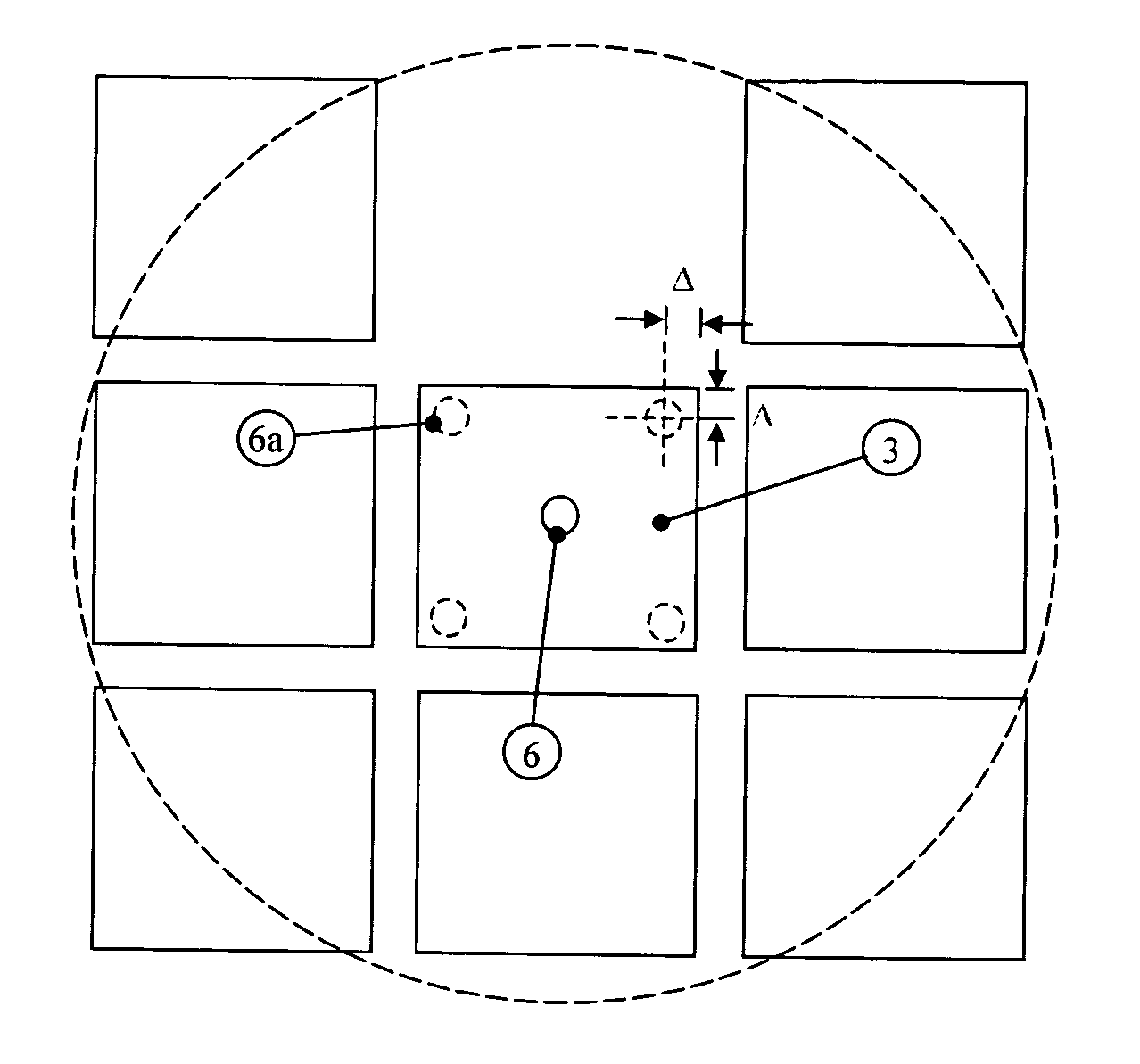
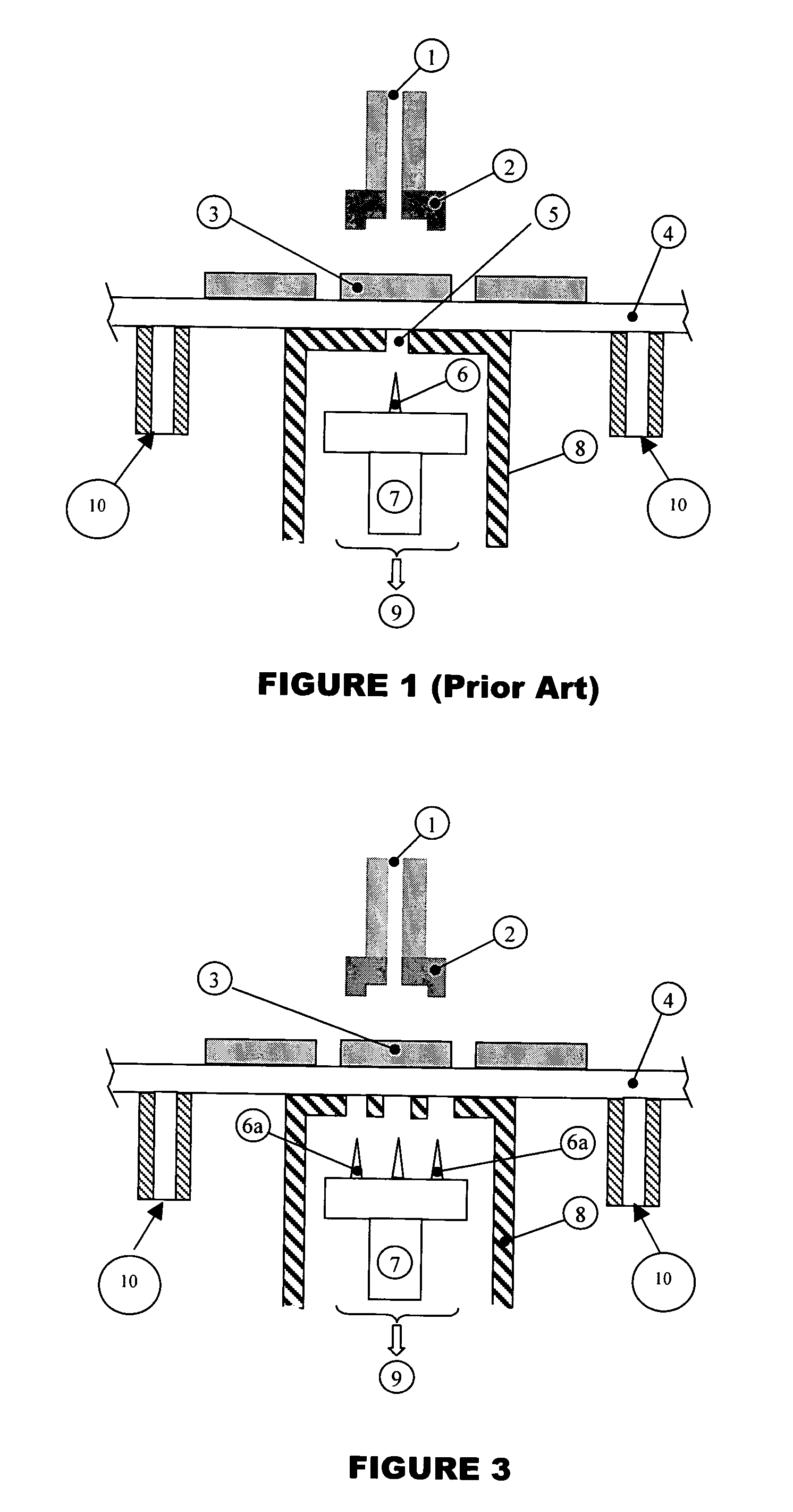
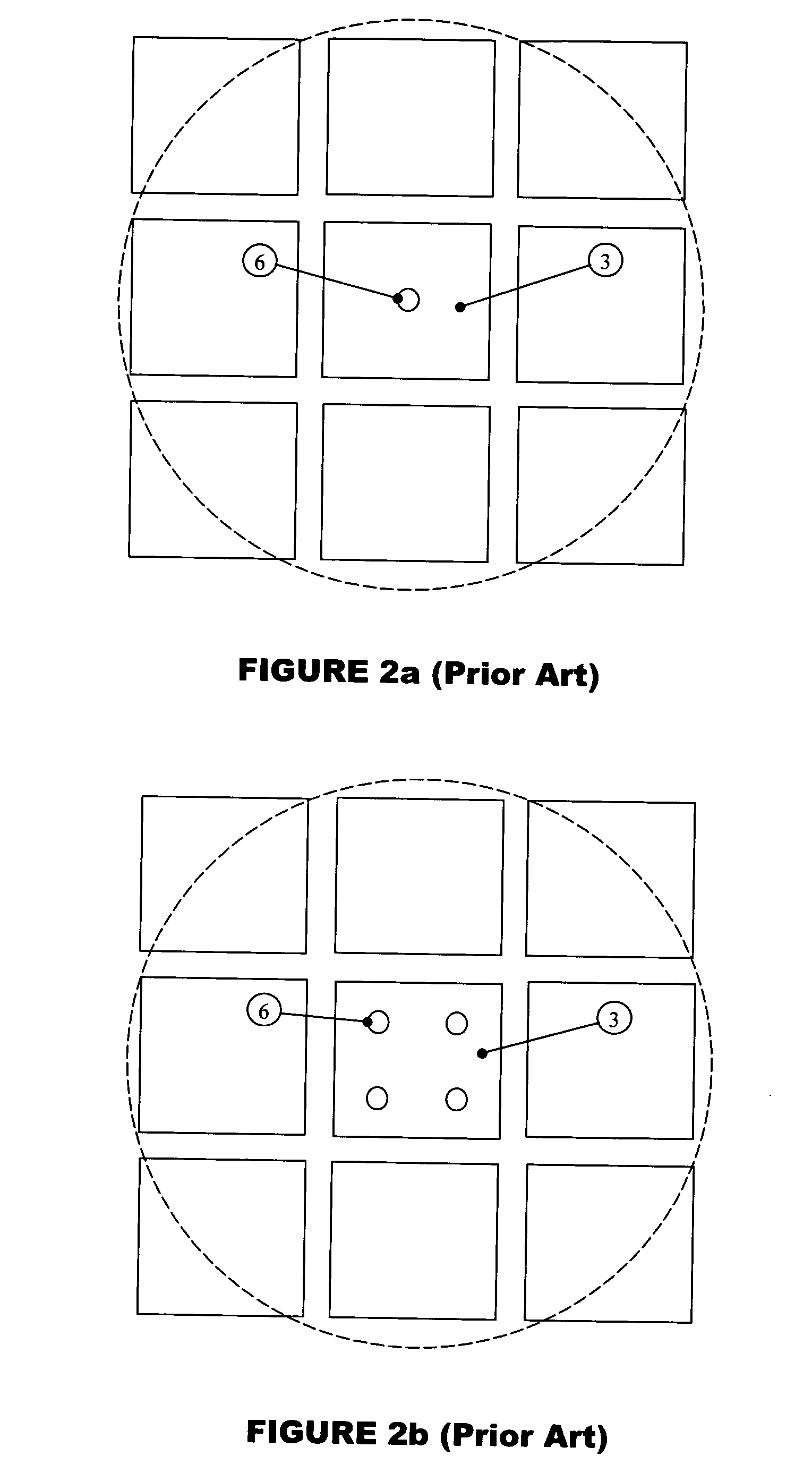
[0017]An ejector device and its peripheral devices for a die detachment process of the prior art are shown in FIG. 1. A plurality of dice 3 are singulated and attached to a plastic adhesive film 4. The plastic adhesive film 4 is mounted to a wafer table with expander (not shown) that moves the dice 3 with respect to a vacuum ejector platform 8. This vacuum ejector platform 8 is an enclosure containing a mechanism driving a chuck 7 supporting one or more ejector pins 6. The chuck 7 provides the mounting holes and brackets for the ejector pins 6 and it is driven up and down by a motorized mechanism (not shown). Moving a die 3 designated to be picked up to the center of the vacuum ejector platform 8 starts a pick-up cycle. The plastic adhesive film 4 is held down against the top surface of the platform 8 by vacuum suction connected to a vacuum suction supply 9 via a hole 5 at the top of the vacuum ejector platform 8 and a periphery of the plastic adhesive film 4 is held down by additio...


PUM


Abstract

The invention provides an apparatus and method for thin die detachment involving the use of a collet for holding and detaching a die mounted on an adhesive surface of an adhesive film. An ejector device comprising a plurality of ejector pins is employed to partially delaminate said die from the adhesive surface for detachment by the collet. Each ejector pin is operative to contact and raise a second surface of the film opposite the adhesive surface at a position substantially at a corner of the die to be detached within a predetermined distance from the edges of said die.

Description

RELATED APPLICATIONS[0001]This application claims the benefit of U.S. Provisional Application Serial No. 60 / 430,010, filed Nov. 27, 2002.FIELD OF THE INVENTION[0002]This invention relates to an apparatus and method of using multiple ejector pins located at specific locations with respect to a die for the detachment of thin dice during die bonding of electronic packages.BACKGROUND AND PRIOR ART[0003]In wafer processing, wafers comprising arrays of semiconductor dice are usually received after dicing on a film frame, and are fed to die bonding machines for placement. In a typical die bonding process, dice are detached and lifted from a film frame comprising plastic adhesive film or a Mylar film and are then transferred to a substrate such as a lead frame or printed wiring board (PWB) substrate. Typically, in a pick-up process, a designated die will first be aligned and moved to a location where push-up pins will rise to raise a die from below while the plastic adhesive film is held do...

Claims


Application Information

Patent Timeline
27 Sep 2011
Publication
US8026126B2
IPC
H01L21/00; H01L21/52; H01L21/78
CPC
H01L21/67092; H01L21/67132; H01L2221/68322; H01L21/78
Inventors
CHEUNG, YIU MING; CHONG, CHI MING