Developer apparatus, an image forming apparatus and an image forming method

a technology of developing apparatus and developing apparatus, applied in the direction of electrographic process apparatus, instruments, optics, etc., can solve the problems of filming, image defects, fog and the like,

Inactive Publication Date: 2011-09-27
SEIKO EPSON CORP
View PDF14 Cites 1 Cited by
  • Summary
  • Abstract
  • Description
  • Claims
  • Application Information

AI Technical Summary

Benefits of technology

[0008]An advantage of some aspects of the invention is to provide technology for preventing problems such as leakage and scattering of toner and fog attributable to creation of toner aggregations in a developer apparatus, an image forming apparatus and an image forming method which use a toner carrier roller whose surface is provided with convexoconcave.
[0010]In the first aspect of the invention constructed as above, by bringing the edge part of the elastic abutting member into contact with the convex sections of the toner carrier roller, the toner is carried in an area (hereinafter, referred to as a “concave section”) which is located between the convex sections and at a shorter distance to the rotational axis of the toner carrier roller than the convex sections and surrounds the convex sections, whereas no toner is carried on the convex sections. Since the toner is not pressed by the restriction member on the convex sections in this way, the formation of toner aggregates resulting from the pressing of the restriction member can be suppressed.
[0012]Mere application of pressing force upon toner carried by the concave sections could flocculate toner or press toner against and fixedly adhere toner to the surface of the toner carrier roller. However, the edge part vibrates to alternately apply and mitigate pressing force upon the concave section according to the above structure. Hence, it is possible to crush toner aggregations which are at or around the concave section. This was confirmed through experiments as described later. According to the invention, destruction of toner aggregations at an early stage makes it possible to prevent growth of larger toner aggregations and hence associated leakage, scattering, fog, filming, etc. In addition, stimulation of toner at or near the concave section attains an effect of increasing the fluidity of the toner and improving the uniformity of a toner layer.
[0015]In these aspects of the invention, similar to the above first aspect of the invention relating to the developer apparatus, the formation of toner aggregates can be suppressed and the formed toner aggregates can be crushed by vibrating the edge part of the elastic abutting member, wherefore the occurrence of problems such as leakage, scattering and fog resulting from the growth of the toner aggregates can be prevented.

Problems solved by technology

However, in the case where a toner carrier roller having the structure above is used, owing to the evenness of the convexoconcave, scattering of toner from the surface of the toner carrier roller, fog and the like will be a problem unless a toner layer thickness on the toner carrier roller is strictly controlled.
They may leak out to outside a developer and get scattered or may adhere to an image carried on the image carrier and cause fog.
Further, toner aggregations thus created may fixedly adhere to the toner carrier roller, thereby resulting in filming, image defects, etc.

Method used


Image

  • Developer apparatus, an image forming apparatus and an image forming method
  • Developer apparatus, an image forming apparatus and an image forming method
  • Developer apparatus, an image forming apparatus and an image forming method

Examples


Embodiment Construction

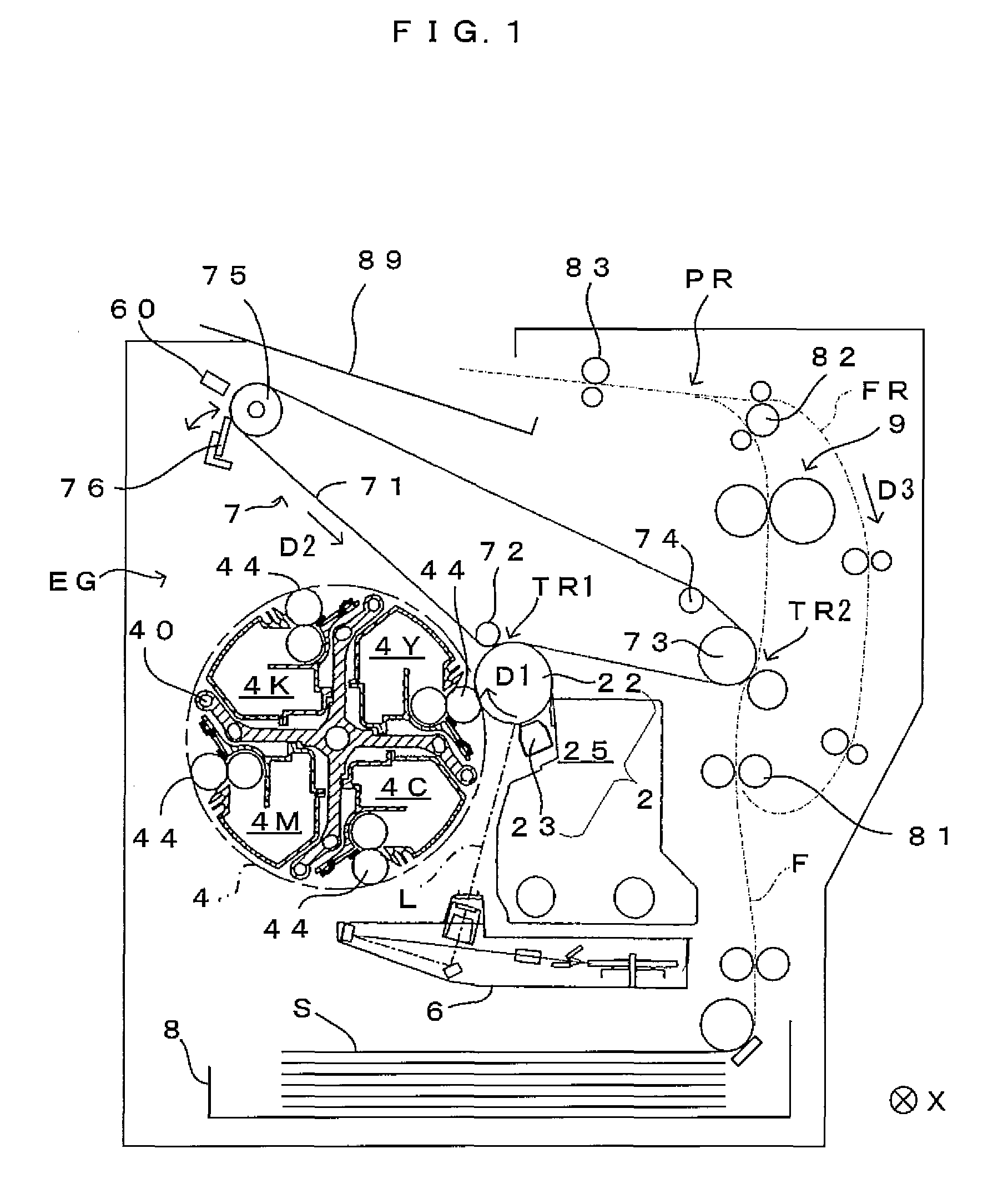
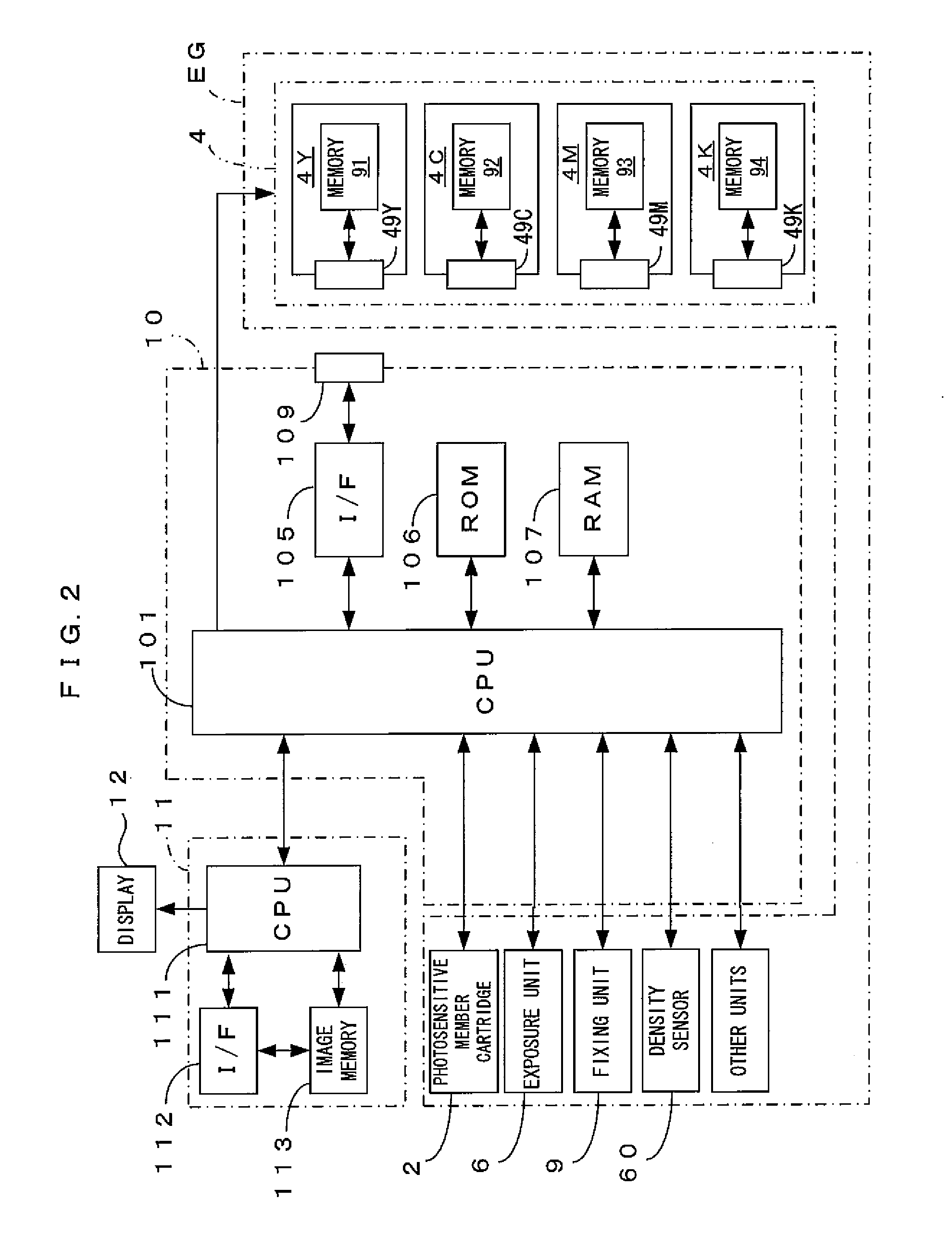
[0032]FIG. 1 is a diagram showing an embodiment of an image forming apparatus according to the invention. FIG. 2 is a block diagram of an electric structure of the image forming apparatus which is shown in FIG. 1. This apparatus is an image forming apparatus which overlays toner (developing powder) in four colors of yellow (Y), cyan (C), magenta (M) and black (K) one atop the other and accordingly forms a full-color image, or forms a monochromatic image using only black (K) toner. In the image forming apparatus, when an image signal is fed to a main controller 11 from an external apparatus such as a host computer, a CPU 101 provided in an engine controller 10 controls respective portions of an engine part EG in accordance with an instruction received from the main controller 11 to perform a predetermined image forming operation, and accordingly, an image which corresponds to the image signal is formed on a sheet S.

[0033]In the engine part EG, a photosensitive member 22 is disposed s...


PUM


Abstract

A developer apparatus includes a toner carrier roller with plural rows of convex sections arranged in width and circumferential directions of the roller. Top surfaces of the convex sections coincide with a curved surface of a single cylinder shaped like the roller. Convex section extending surfaces obtained by extending the top surfaces of the convex sections in the width direction overlap between convex sections belong to the same row and do not overlap between convex sections belonging to different rows. A width in the circumferential direction of a restriction nip formed by contact of an elastic abutting member of a restriction member with the roller is smaller than a spacing between two convex sections belonging to convex section rows that are adjacent in the circumferential direction.

Description

CROSS REFERENCE TO RELATED APPLICATION[0001]The disclosure of Japanese Patent Application No. 2007-314663 filed on Dec. 5, 2007 including specification, drawings and claims is incorporated herein by reference in its entirety.BACKGROUND[0002]1. Technical Field[0003]The present invention relates to a developer apparatus which comprises a toner carrier roller whose surface carries toner, and an image forming apparatus for and an image forming method of developing an electrostatic latent image with toner using this roller.[0004]2. Related Art[0005]In techniques for developing an electrostatic latent image carried on an image carrier with toner, an apparatus is widely used which includes a toner carrier roller which is shaped approximately like a cylinder, carries toner on a surface thereof, and is arranged opposed facing the image carrier. For the purpose of improving the characteristics of toner carried on the surface of such a toner carrier roller, the applicant of the present applica...

Claims


Application Information

Patent Timeline
Patent Type & Authority Patents(United States)
IPC IPC(8): G03G15/09
CPCG03G15/0818G03G2215/0863
Inventor YAMADA, YOICHIMAEDA, MASAHIROFUKUMOTO, TAKATOMO
Owner SEIKO EPSON CORP
Why Eureka
Try Eureka