RF connector assembly

a technology of connectors and connector parts, applied in the direction of coupling devices, two-part coupling devices, electrical apparatus, etc., can solve the problems of contact damage, contact axes of connectors not being properly aligned, and affecting the service life of the connector, so as to restrict the lateral movement of the electrical connectors

Active Publication Date: 2011-10-04
TYCO ELECTRONICS LOGISTICS AG (CH)
View PDF9 Cites 37 Cited by
  • Summary
  • Abstract
  • Description
  • Claims
  • Application Information

AI Technical Summary

Benefits of technology

[0006]In one embodiment, an electrical connector assembly is provided having a housing that has an insert and an organizer separate from, and coupled to, the insert. The insert and the organizer have insert openings and organizer openings aligned with corresponding insert openings. The organizer openings have a smaller diameter than the insert openings and the insert openings have a lip that extends into the insert opening. Electrical connectors are received in the housing that have shells and include clips surrounding corresponding shells. The clips engage the lips of the insert openings for securing the electrical connectors in the insert openings. The organizer openings circumferentially surround the shells and restrict lateral movement of the electrical connectors.
[0007]In another embodiment, an electrical connector system is provided having an electrical connector assembly that includes a housing that has an insert and an organizer separate from, and coupled to, the insert. The insert and the organizer have insert openings and organizer openings aligned with corresponding insert openings. The organizer openings have a smaller diameter than the insert openings. The insert openings have a lip extending into the insert opening. Electrical connectors are received in the housing that have shells and include clips surrounding corresponding shells. The clips engage the lips of the insert openings for securing the electrical connectors in the insert openings. The organizer openings circumferentially surround the shells and restrict lateral movement of the electrical connectors. The electrical connector system also includes an RF module having a housing that has walls that define a connector cavity and RF connectors received in the connector cavity. The electrical connector assembly is mated with the RF module such that the electrical connectors are mated with corresponding RF connectors.

Problems solved by technology

During mating, the contact axes of the connectors may not be properly aligned with one another due to the lateral movement of the connectors.
The spring thus forces the connector in an undesired direction and may cause damage to the contacts.
Additionally, when both connectors are tilted off-center, there is a greater chance that the contacts are not properly aligned and may be damaged during mating.

Method used


Image

  • RF connector assembly
  • RF connector assembly
  • RF connector assembly

Examples


Embodiment Construction

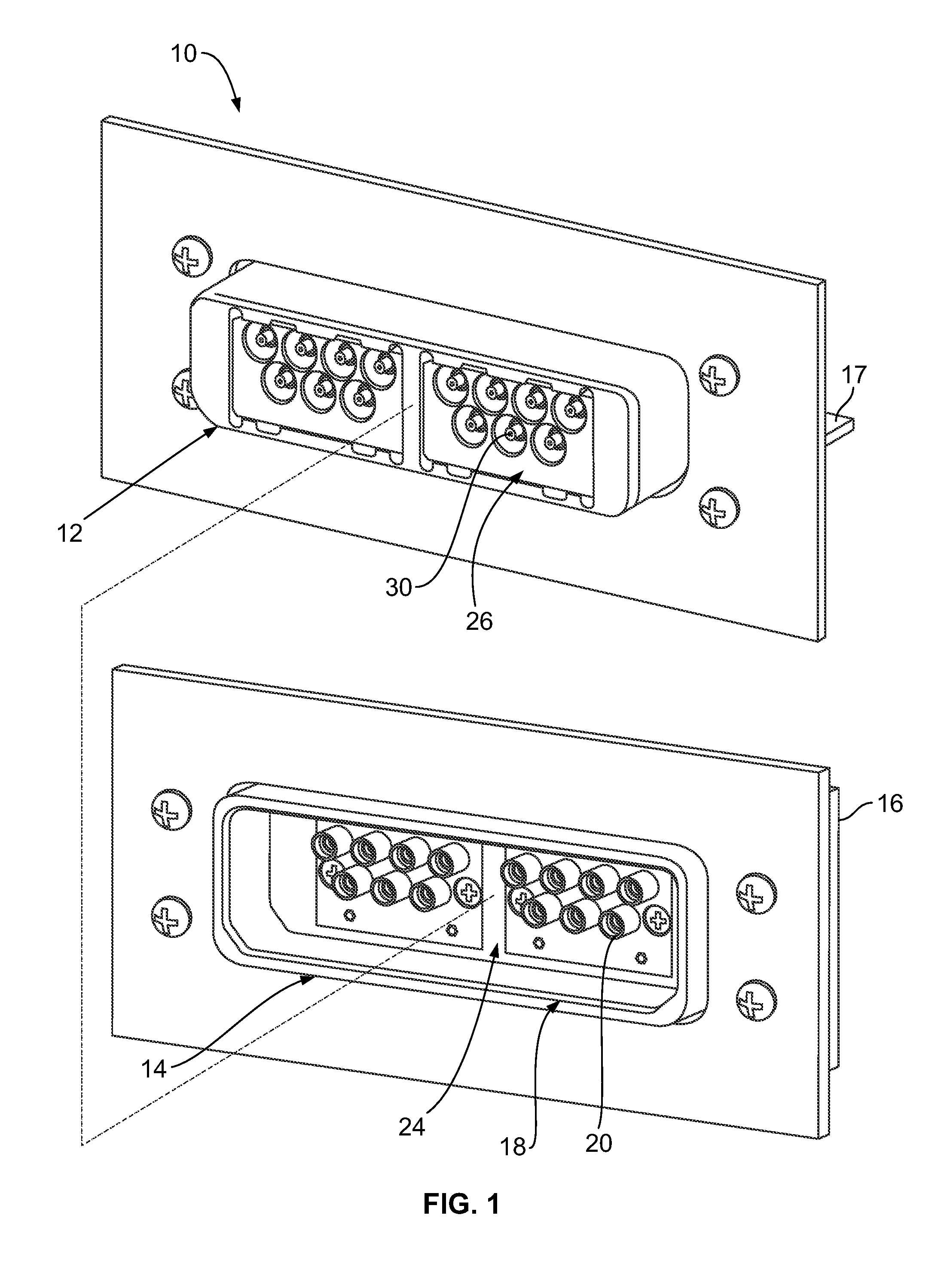
[0020]FIG. 1 illustrates an electrical connector system 10 including an RF module 12 and an electrical connector assembly 14 formed in accordance with an exemplary embodiment. FIG. 1 shows front perspective views of both the RF module 12 and the electrical connector assembly 14, which are configured to be mated together along the phantom line shown in FIG. 1. In an exemplary embodiment, the electrical connector assembly 14 defines a motherboard assembly that is associated with a motherboard 16. The RF module 12 defines a daughtercard assembly that is associated with a daughtercard 17.

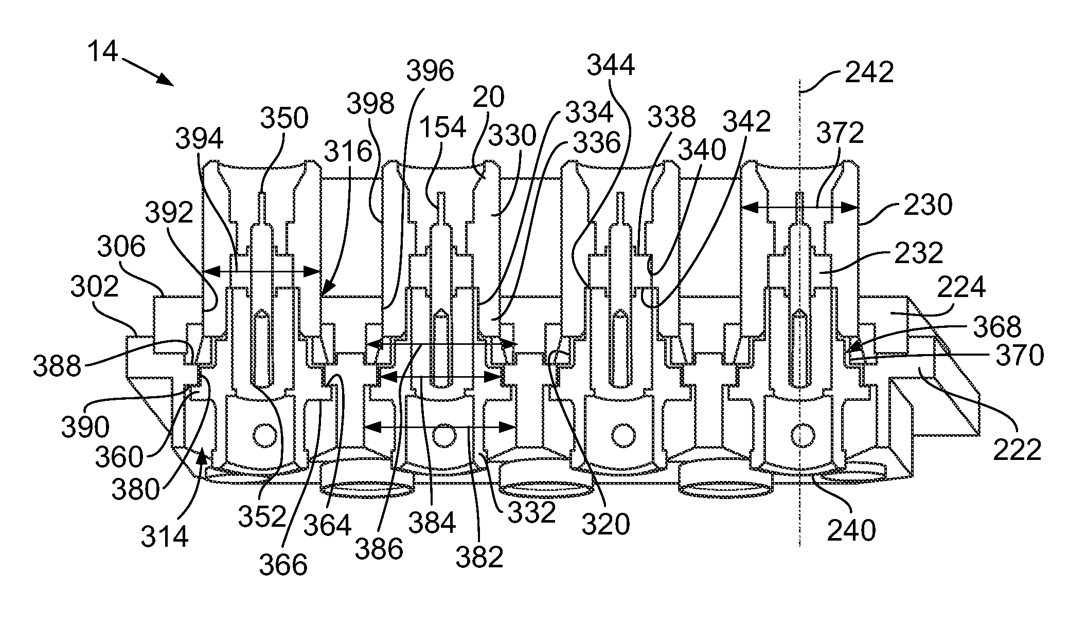
[0021]The electrical connector assembly 14 includes a housing 18 and a plurality of electrical connectors 20 held within the housing 18. Any number of electrical connectors 20 may be utilized depending on the particular application. In the illustrated embodiment, seven electrical connectors 20 are provided in two rows. The electrical connectors 20 are cable mounted to respective coaxial cables 22 (shown...


PUM


Abstract

An electrical connector assembly includes a housing that has an insert and an organizer separate from, and coupled to, the insert. The insert and the organizer have insert openings and organizer openings aligned with corresponding insert openings. The organizer openings have a smaller diameter than the insert openings and the insert openings have a lip that extends into the insert opening. Electrical connectors are received in the housing that have shells and include clips surrounding corresponding shells. The clips engage the lips of the insert openings for securing the electrical connectors in the insert openings. The organizer openings circumferentially surround the shells and restrict lateral movement of the electrical connectors.

Description

BACKGROUND OF THE INVENTION[0001]The subject matter herein relates generally to electrical connector assemblies, and more particularly to RF connectors.[0002]Due to their favorable electrical characteristics, coaxial cables and connectors have grown in popularity for interconnecting electronic devices and peripheral systems. Typically, one connector is mounted to a circuit board of an electronic device at an input / output port of the device and extends through an exterior housing of the device for connection with a coaxial cable connector. The connectors include an inner conductor coaxially disposed within an outer conductor, with a dielectric material separating the inner and outer conductors.[0003]A typical application utilizing coaxial cable connectors is a radio-frequency (RF) application having RF connectors designed to work at radio frequencies in the UHF and / or VHF range. RF connectors are typically used with coaxial cables and are designed to maintain the shielding that the c...

Claims


Application Information

Patent Timeline
Patent Type & Authority Patents(United States)
IPC IPC(8): H01R13/434
CPCH01R13/518H01R24/52H01R13/4367H01R2103/00H01R13/6315H01R13/506H01R13/748H01R13/582
Inventor YI, CHONG HUNMORLEY, STEPHEN J.
Owner TYCO ELECTRONICS LOGISTICS AG (CH)
Why Eureka
Try Eureka