Linear motor and linear motor cogging reduction method

a technology of linear motors and cogging reduction, applied in the field of linear motors, to achieve the effect of reducing the cogging of the whole core, reducing the influence, and reducing the cogging reliably

Active Publication Date: 2011-10-04
THK CO LTD
View PDF15 Cites 11 Cited by
  • Summary
  • Abstract
  • Description
  • Claims
  • Application Information

AI Technical Summary

Benefits of technology

[0019]In some exemplary embodiments of the invention, as the auxiliary core is arranged substantially at the position an odd multiple of a magnetic pole pitch×¼ away from the center salient pole, it is possible to generate such a cogging force at the auxiliary core as to cancel the cogging force generated by the center salient force. This means that it is possible to reduce the cogging of the whole core.
[0020]In some exemplary embodiments of the invention, as the gap is made between the core and the auxiliary core or the non-magnetic material is interposed therebetween, it is possible to prevent the salient poles at the respective ends of the core and the auxiliary core from forming a magnetic circuit. Hence, it is possible to reduce the influence of the conventional measure against cogging that strengthens the magnetic flux of the salient poles at the respective ends of the core, thereby to reduce the cogging reliably. In addition, as the core and auxiliary core are separate components, even when there is an error in design values in dimensions of the manufactured auxiliary core, or besides the components of the linear motor, a component that causes cogging is provided between the stator and the mover, there is no need to manufacture the core again, of which manufacturing process is complicated, and only need to change the auxiliary core.
[0021]In some exemplary embodiments of the invention, the auxiliary core can be separated from the core while maintaining the pitch between the auxiliary core and the center salient pole constant. Hence, it is possible to prevent the salient poles at the respective ends of the core and the auxiliary core from forming a magnetic circuit. Besides, the base part is thicker than the tip end part, the auxiliary core can be easily attached to the table or the like. Further, as the attraction applied to the auxiliary core can be reduced, it becomes possible to reduce a load on a guide part for guiding linear movement of the mover.
[0022]In some exemplary embodiments of the invention, it is possible to shorten the entire length of the core including the auxiliary core while the gap is made between the salient poles at the respective ends of the core and the auxiliary core.
[0023]In some exemplary embodiments of the invention, it is possible to evenly reduce the cogging force generated by the center salient pole, in a balanced manner, with use of the auxiliary cores provided at the respective sides of the armature.
[0024]In some exemplary embodiments of the invention, it is possible to reduce the cogging force at the center salient pole among the three salient poles effectively.

Problems solved by technology

Even if a current is passed through the coils, there remains cogging, which acts as disturbance.

Method used


Image

  • Linear motor and linear motor cogging reduction method
  • Linear motor and linear motor cogging reduction method
  • Linear motor and linear motor cogging reduction method

Examples


examples

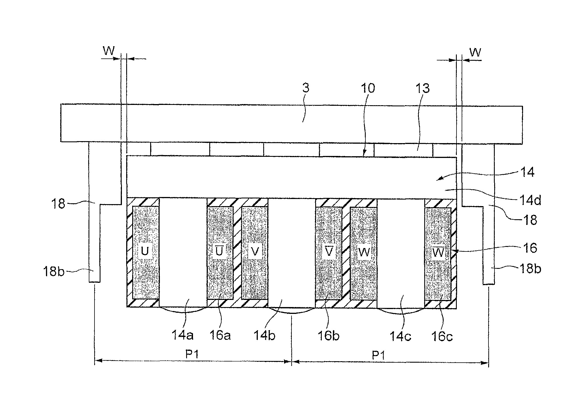
[0057]A linear motor is used of which the magnetic pole pitch between N-N poles of the field magnet part 5 is 39 mm. When this is applied to the formula shown in FIG. 9, the distance P1 between the center of the salient pole 14b of W phase and the center of the auxiliary core 18 is 39×(¼)×5=48.75 mm. In fact, the auxiliary core 18 is arranged at the position of 39×(¼)×4.8=46.8 mm. Then, cogging is compared between before and after mounting of the auxiliary core 18.

[0058]FIGS. 10A and 10B illustrate results of cogging comparison. FIG. 10A illustrates the cogging before mounting of the auxiliary core 18 and FIG. 10B illustrates the cogging after mounting of the auxiliary core 18. These show that the cogging force can be reduced about 50% from 11.4 N to 5.86 N by mounting of the auxiliary core 18.

[0059]The present invention is not limited to the above-described exemplary embodiment and may be embodied in various forms without departing from the scope of the present invention. For examp...


PUM


Abstract

Provided is a linear motor capable of reducing cogging. The linear motor has a field magnet part 5 having a plurality of permanent magnets 21 arranged to form N and S poles alternately; a core 14 having a plurality of salient poles 14a, 14b and 14c arranged facing the field magnet part 5; and a three-phase coil 16 wound around the salient poles 14a, 14b and 14c of the core 14. At respective sides in the moving direction of an armature having the three-phase coil 16 and the core 14, auxiliary cores 18 made of a magnetic material are provided to sandwich the armature 10. The distance P1 between a center of each auxiliary core and a center of a center salient pole 14b is set to be substantially ¼×(2N+1)×a magnetic pole pitch between N poles of the field magnet part 5 (N: an integer equal to or greater than 1).

Description

TECHNICAL FIELD[0001]The present invention relates to a linear motor having moving a mover which moves linearly relative to a stator and, more particularly, to a linear motor having an auxiliary core so as to reduce cogging of the linear motor and a cogging reduction method thereof.BACKGROUND ART[0002]In a linear motor, a mover is moved linearly relative to a stator. In the stator of the linear motor, a plurality of permanent magnets is arranged so as the N and S magnetic poles are formed alternately. On the stator, the mover is arranged via a gap. In order to maintain the gap constant between the stator and the mover, linear movement of the mover is guided by a guide device such as a linear guide or a bearing.[0003]In the mover, a magnetic body core is provided facing the permanent magnets. The core has a plurality of salient poles projecting toward a field magnet part. The plural salient poles are wounded with three-phase coils of U, V and W phases, respectively. When a three-phas...

Claims


Application Information

Patent Timeline
Patent Type & Authority Patents(United States)
IPC IPC(8): H02K41/03
CPCH02K41/03H02K29/03H02K2201/06
Inventor ASO, TOSHIYUKIKANESHIGE, HIROSHITANAAMI, AKIE
Owner THK CO LTD
Why Eureka
Try Eureka