Image capturing device with field limiting parts and method of capturing an image using field limiting parts

a technology of image capturing and field limiting parts, which is applied in the field of image capturing devices and methods of capturing images, can solve the problems of insufficient peripheral vision light intensity, etc., and achieve the effect of simple image capturing device structure and better images without optical aberration or distortion

Inactive Publication Date: 2011-10-04
FUJIFILM CORP
View PDF19 Cites 11 Cited by
  • Summary
  • Abstract
  • Description
  • Claims
  • Application Information

AI Technical Summary

Benefits of technology

[0009]In the aforementioned image capturing device, the control device may correct exposure time or gain of the light sensor in accordance with a position of the scanning spot, so as to equalize an exposure level at all positions of the scanning spot. Alternatively, the control device may correct gain of the light sensor in accordance with movement speed of the scanning spot at each position of the scanning spot, so as to equalize an exposure level at all positions of the scanning spot.
[0010]With this construction of the image capturing device, even in the case where the light intensity detected by the light sensor contains an error in accordance with a position of the scanning spot, it is possible to equalize the exposure level at all positions of the scanning spot by adjusting the exposure time or by adjusting the gain of the light sensor.
[0012]Further, in the aforementioned image capturing device, the light sensor may include a plurality of color filters for dividing light, and light detection elements each corresponding to the color filters. This construction of the image capturing device makes it possible to acquire color image information, for example, divided by three primary colors including R, G, and B.
[0018]According to the present invention, in the aforementioned image capturing device and the aforementioned image capturing method, at least two field limiting parts limit the field of view and the light sensor detects the light intensity of one scanning spot. Therefore, it is not necessary to provide a lens, and this results in a simple structure of the image capturing device as well as obtaining better images without optical aberration or distortion.

Problems solved by technology

However, an optical lens inevitably causes optical aberration or distortion, and insufficient light intensity at peripheral vision.

Method used


Image

  • Image capturing device with field limiting parts and method of capturing an image using field limiting parts
  • Image capturing device with field limiting parts and method of capturing an image using field limiting parts
  • Image capturing device with field limiting parts and method of capturing an image using field limiting parts

Examples


first embodiment

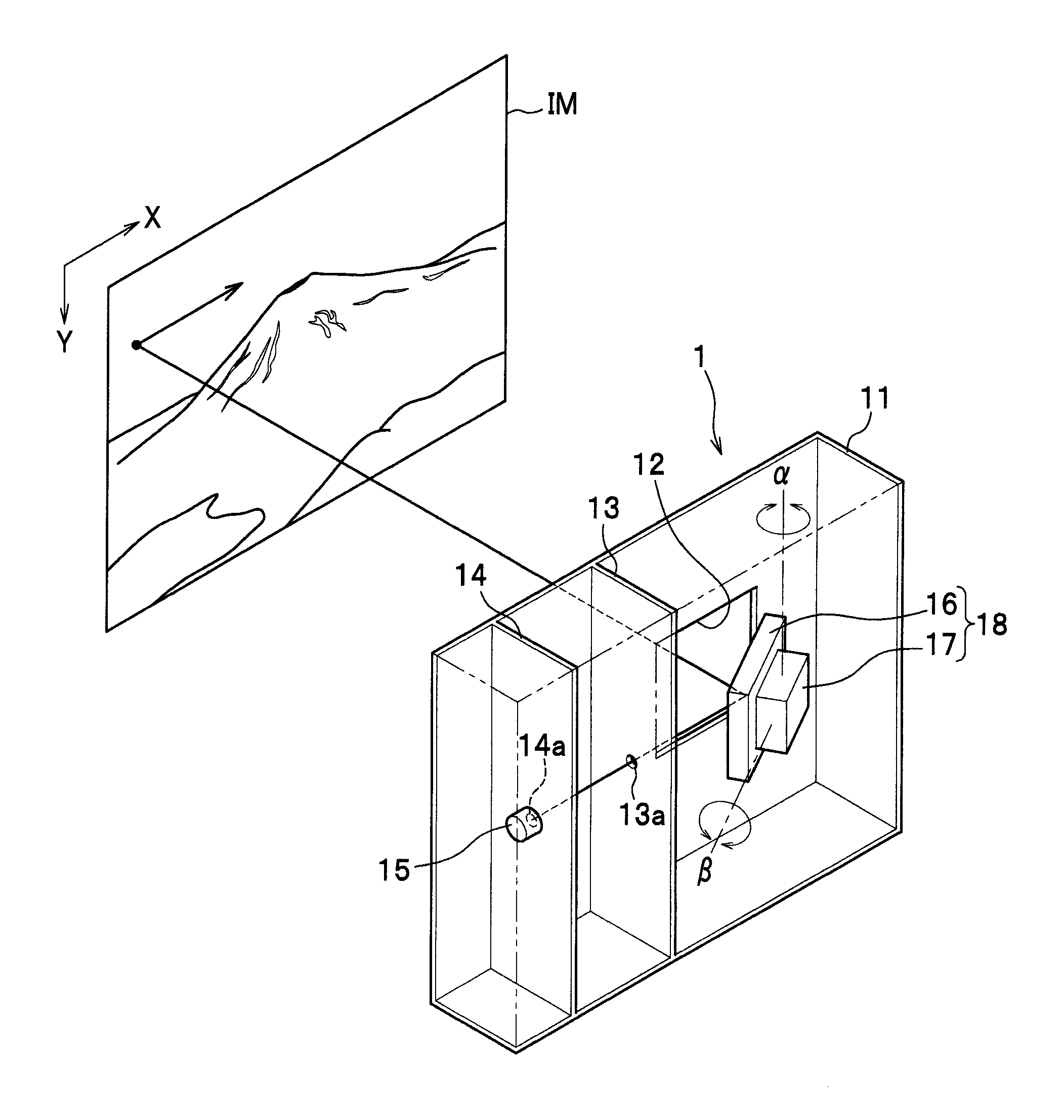
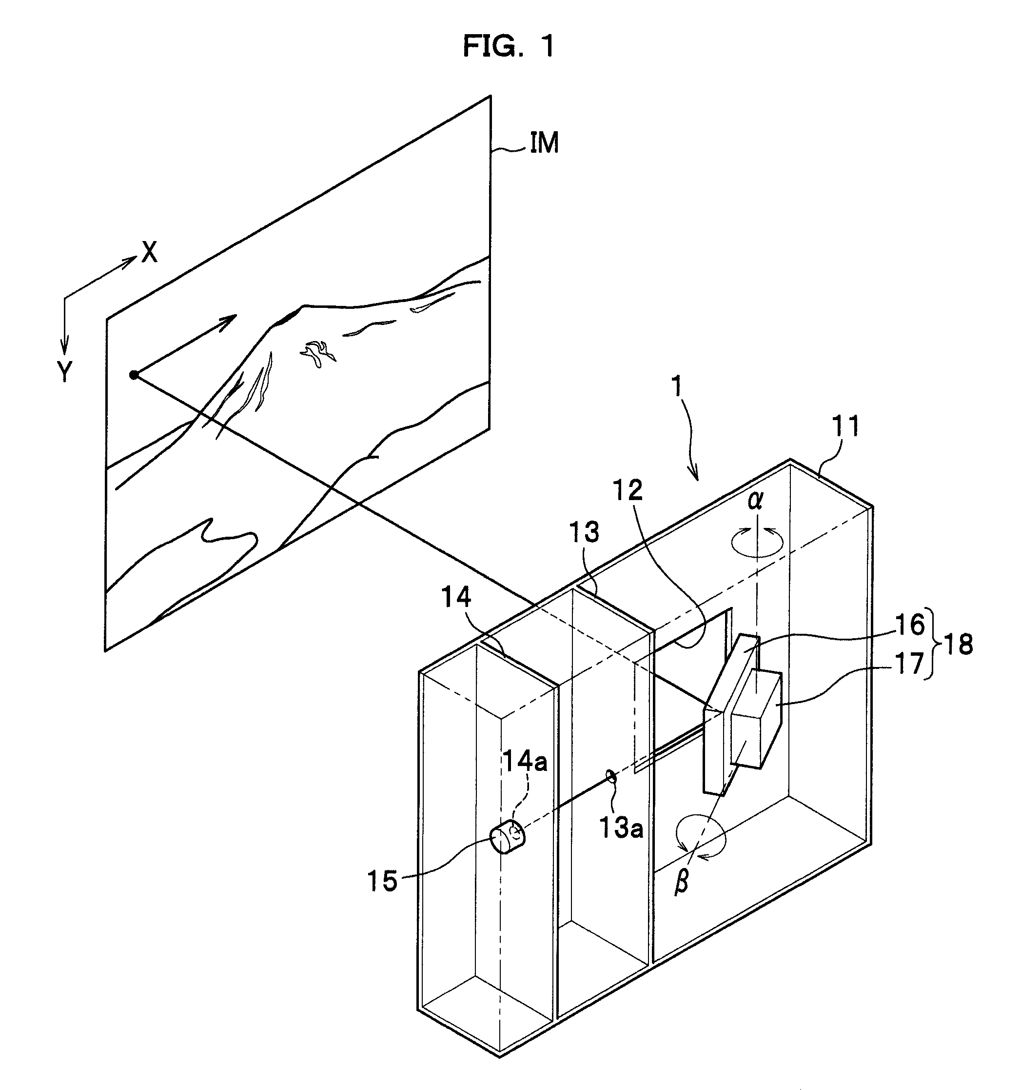
[0028]As seen in FIG. 1, an image capturing device 1 scans and captures an image IM as electronic data.

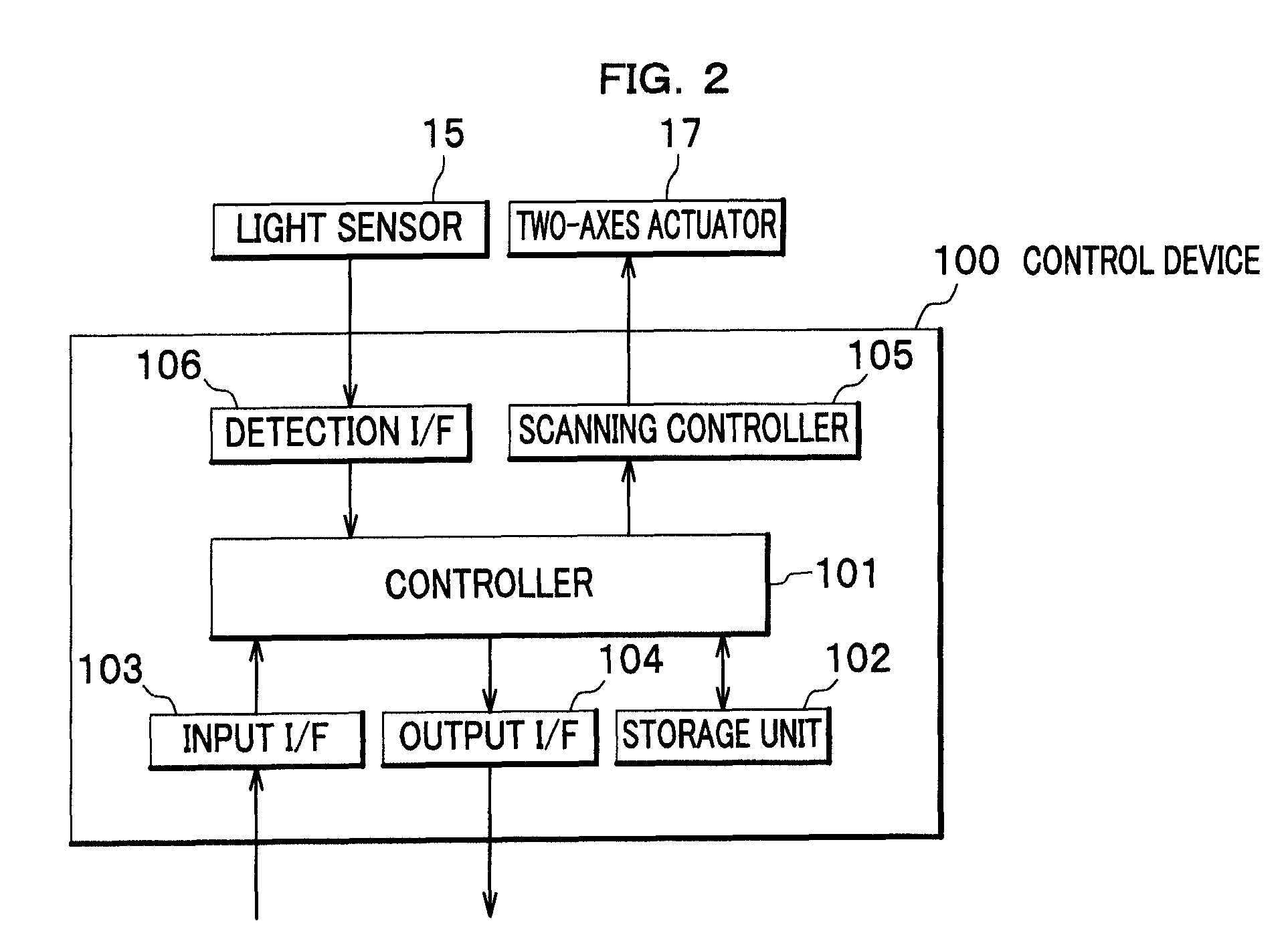
[0029]The image capturing device 1 includes a casing 11, a galvanometer mirror 18, and a light sensor 15. The galvanometer mirror 18 is controlled by a control device 100 as shown in FIG. 2.

[0030]The casing 11 is provided with a window 12 for obtaining light at a surface facing to the image IM. The galvanometer mirror 18 is arranged in the casing 11 opposite to the window 12. The casing 11 is divided by partition walls 13, 14 into three rooms. Each partition wall 13, 14 has a dot-like opening 13a,14a, which allows a part of light reflected by the galvanometer mirror 18 to be passed through. The light sensor 15 is arranged at the opening 14a of the partition wall 14 so as to detect light that has passed through the opening 14a. In other words, the openings 13a, 14a limit a field of view to a dot-like section to define a passage of light. These openings 13a, 14a are field limiting pa...

second embodiment

[0045]With reference to FIGS. 4A to 4C, an image capturing device according to a second embodiment will be described below. In the following description, parts similar to those previously described with reference to the first embodiment are denoted by the same reference numerals, and detailed description thereof will be omitted.

[0046]As seen in FIG. 4A, an image capturing device 2 includes a casing 21, and a window 22 is formed in the casing 21 at a surface facing to an image IM. The casing 11 is partitioned by a field limiting wall 23 and a partition wall 24. The field limiting wall 23 forms an opening 23a as the field limiting part by which the image IM can be scanned along the X-axis direction and the Y-axis direction of the image IM to be captured. The partition wall 24 also forms an opening 24a as the field limiting part. A light sensor 25 is provided at the opening 24a of the partition wall 24.

[0047]As long as it can scan the image IM with the opening 23a along the X-axis and ...

third embodiment

[0051]With reference to FIG. 5, an image capturing device according to a third embodiment will be described below. In the following description, parts similar to those previously described with reference to the first embodiment are denoted by the same reference numerals, and detailed description thereof will be omitted.

[0052]As seen in FIG. 5, an image capturing device 3 includes a casing 31, a field limiting block 33 as a field limiting member which is positioned in the casing 31, a light sensor 35, a two-axes actuator 37, and a control device (not shown) which is similar to that of the first embodiment.

[0053]The casing 31 is provided with a window 32 at a surface facing to the image IM, and the field limiting block 33 is arranged in the casing 31 opposite to the window 32.

[0054]The field limiting block 33 is an elongate member whose longitudinal axis extends in the direction toward the image IM, and an elongated through-hole 33a is formed along the longitudinal direction of the fi...


PUM


Abstract

An image capturing device includes: at least two field limiting parts which limit a field of view to a dot-like section to define a passage of light; a light sensor which detects light passing through the field limiting parts; a scanning device which moves a scanning spot defined by the dot-like section in two-dimensional directions within a scanning area of an image to be captured; and a control device which controls movements of the scanning spot by the scanning device while receiving detection signals from the light sensor.

Description

CROSS REFERENCE TO RELATED APPLICATIONS[0001]This application claims the foreign priority benefit under Title 35, U.S. Code, §119(a)-(d) of Japanese Patent Application No. 2007-001429 filed on Jan. 9, 2007 in the Japan Patent Office, the disclosure of which is herein incorporated by reference in its entirety.FIELD OF THE INVENTION[0002]The present invention relates to an image capturing device and a method of capturing an image.BACKGROUND OF THE INVENTION[0003]As disclosed in Japanese Laid-open Patent Application No. 2006-295949, generally, when taking a picture with a digital camera, a scene is focused through a lens on two-dimensional image sensors such as CCD image sensors or CMOS image sensors, where an image of the scene is obtained as electronic data.[0004]However, an optical lens inevitably causes optical aberration or distortion, and insufficient light intensity at peripheral vision. In order to obtain a better image, it is necessary to combine a plurality of lenses, which w...

Claims


Application Information

Patent Timeline
Patent Type & Authority Patents(United States)
IPC IPC(8): H04N5/225
CPCH04N1/113H04N1/2112H04N2101/00H04N2201/0084
Inventor USAMI, YOSHIHISA
Owner FUJIFILM CORP
Why Eureka
Try Eureka