Silicone spray tip

a technology of silicon dioxide and spray tip, applied in the direction of liquid transferring device, combustion type, lighting and heating apparatus, etc., can solve the problem of impossible application of the solution

Active Publication Date: 2011-10-11
CONFLUENT SURGICAL
View PDF97 Cites 165 Cited by
  • Summary
  • Abstract
  • Description
  • Claims
  • Application Information

AI Technical Summary

Problems solved by technology

Mixing of the components too soon before application may result in premature hardening of the mixture, thereby making application of the solution impossible.

Method used


Image

  • Silicone spray tip
  • Silicone spray tip
  • Silicone spray tip

Examples


Embodiment Construction

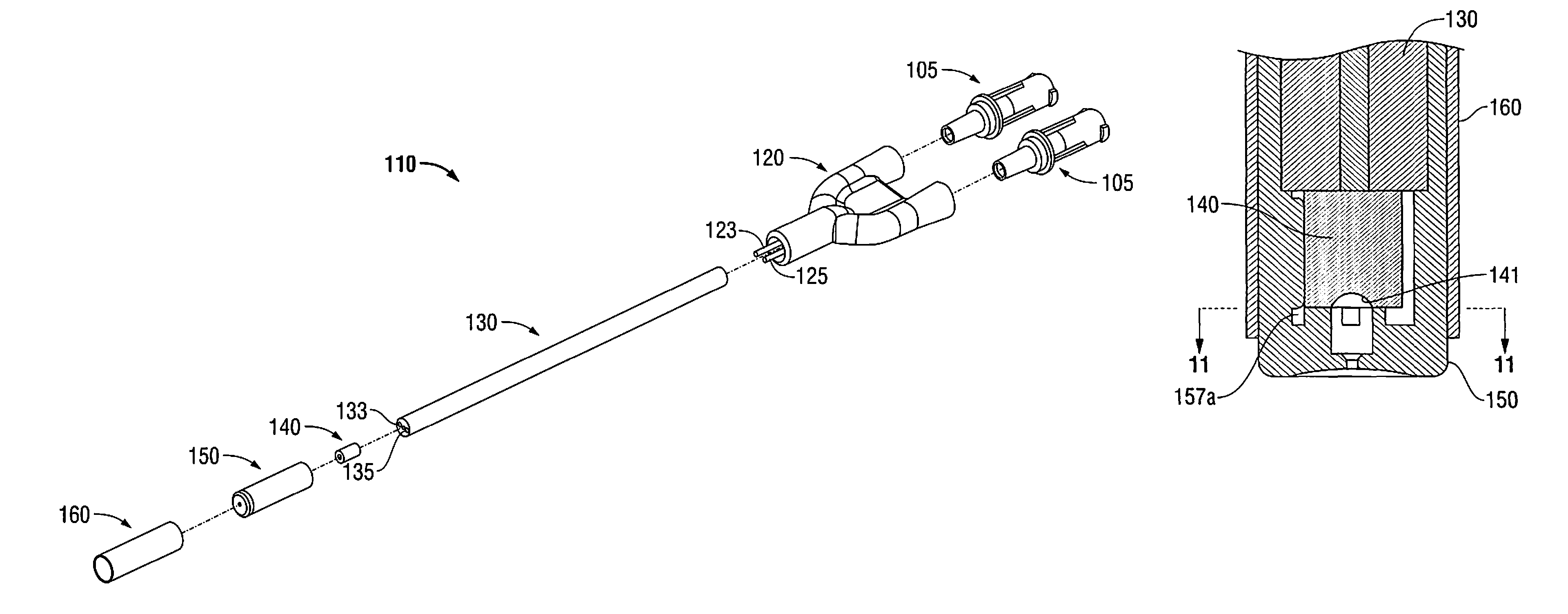
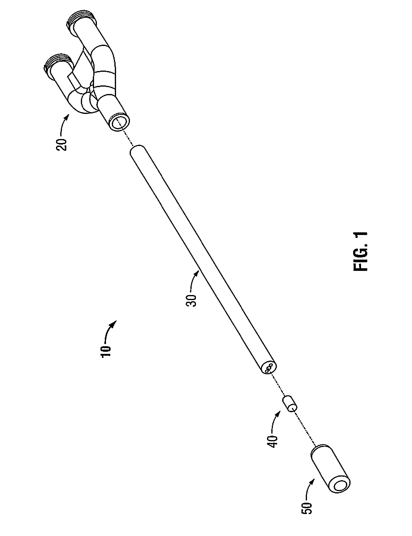
[0022]Referring initially to FIG. 1, an applicator assembly including a spray tip assembly according the present disclosure is shown generally as applicator assembly 10. Applicator assembly 10 includes a manifold or base 20, an elongated shaft 30 extending from manifold 20, and a spray tip assembly 50 positioned on a distal end 30b of elongated shaft 30. Applicator assembly 10 further includes an insert 40 configured to be received within spray tip assembly 50 and located distal of elongated shaft 30.

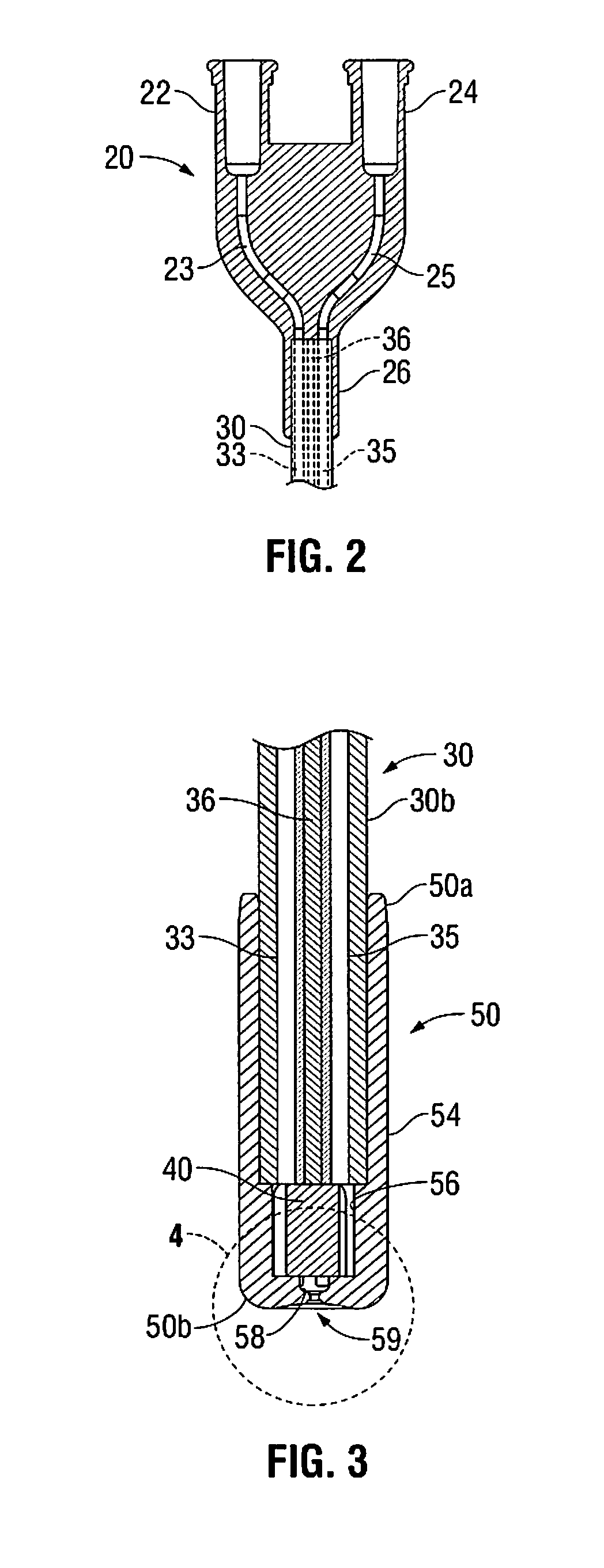
[0023]With reference now to FIG. 2, manifold 20 includes a substantially Y-shaped member having a first and a second proximal extension 22, 24 and a distal extension 26. Proximal extensions 22, 24 are configured for operable engagement with a first and a second source of component (not show), e.g., syringe. Distal extension 26 is configured for operable engagement with elongated shaft 30, as will be discussed in further detail below. Manifold 20 further includes first and second compone...


PUM


Abstract

An applicator assembly for mixing at least a first and a second component is provided. The applicator assembly includes a manifold configured for operable engagement with first and second source of component, the manifold including first and second component channels therethrough, an elongated shaft extending distally from the manifold, the elongated shaft including first and second component lumens extending the length thereof, the first and second component channels in fluid communication with the first and second component lumens, a tip assembly defining a first chamber, an intermediate chamber and a final chamber, wherein the first chamber is configured to receive a distal end of the elongated shaft, the second chamber is configured to receive an insert, and the final chamber is configured to receive the first and second components prior to the mixture being ejected from an outlet defined in the distal end of the tip assembly.

Description

CROSS-REFERENCE TO RELATED APPLICATION[0001]The present application claims the benefit of and priority to U.S. Provisional Application Ser. No. 61 / 047,826, filed on Apr. 25, 2008, the entire content of which is incorporated herein by reference.BACKGROUND[0002]1. Technical Field[0003]The present disclosure relates to assemblies for mixing and applying two or more components. More particularly, the present disclosure relates to a spray tip for use with an applicator assembly for mixing two or more components.[0004]2. Background of Related Art[0005]Applicator assemblies for dispensing two or more components are known. Typically, such assemblies are used for applying bioadhesives, polymers and other synthetic material used in wound closure. Because of the reactant nature of the components used to form the bioadhesive, mixing of the components does not occur until the solution is ready to be applied. Mixing of the components too soon before application may result in premature hardening o...

Claims


Application Information

Patent Timeline
Patent Type & Authority Patents(United States)
IPC IPC(8): B05D7/10B01F25/70
CPCA61B17/00491B01F5/0057B01F13/0027B01F15/0087B01F5/0656B05B7/0408B05B7/10B05B15/0291B05B15/066B05B1/3436A61B2017/00495B01F2005/0637Y10S239/12B05B15/652B05B15/528B01F25/10B01F25/431972B01F25/434B01F33/50114B01F35/522
Inventor FORTIER, JASONHULL, LESDRISCOLL, ARTHUR
Owner CONFLUENT SURGICAL
Why Eureka
Try Eureka