Intake manifold

a technology of intake manifold and manifold, which is applied in the direction of air intake for fuel, combustion-air/fuel-air treatment, machines/engines, etc., can solve the problems of connector b>106/b> not being long or inclined, and fuel system damag

Inactive Publication Date: 2011-10-18
DENSO CORP
View PDF4 Cites 12 Cited by
  • Summary
  • Abstract
  • Description
  • Claims
  • Application Information

AI Technical Summary

Benefits of technology

[0013]Accordingly, if the intake manifold is broken due to a large impact applied to the automobile, the cover prevents the second piece from moving upward, such that the possibility that a broken part of the intake manifold damages a fuel system can be reduced.
[0015]Accordingly, if the intake manifold is broken due to a large impact applied to the automobile, the cover prevents the second piece from moving upward, such that the possibility that a broken part of the intake manifold damages a fuel system can be reduced.

Problems solved by technology

In this case, the fuel system may be damaged.
However, the connector 106 may not be able to be long or inclined, based on mounting conditions of a variety of devices in an engine compartment.

Method used


Image

  • Intake manifold
  • Intake manifold
  • Intake manifold

Examples


Embodiment Construction

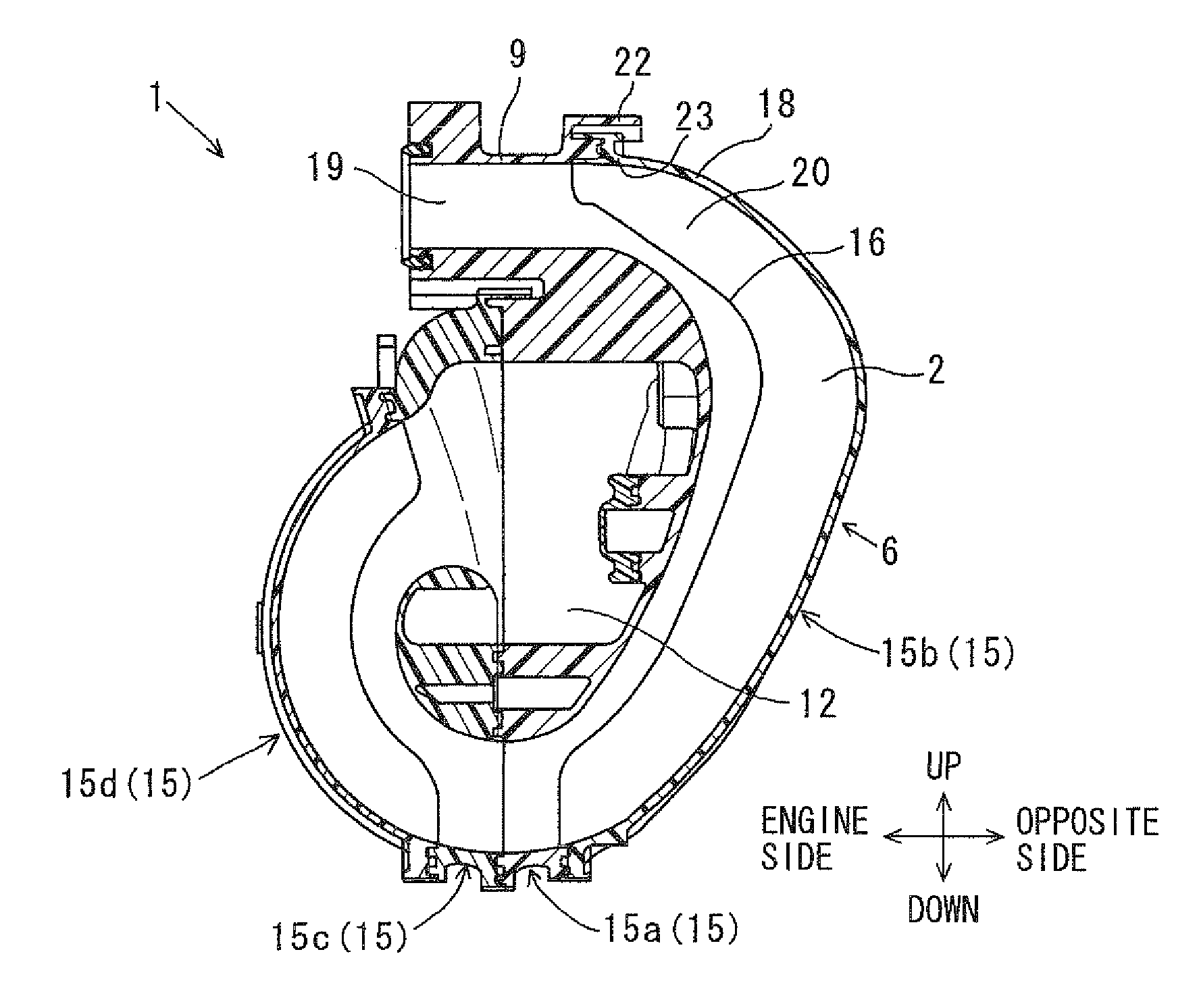
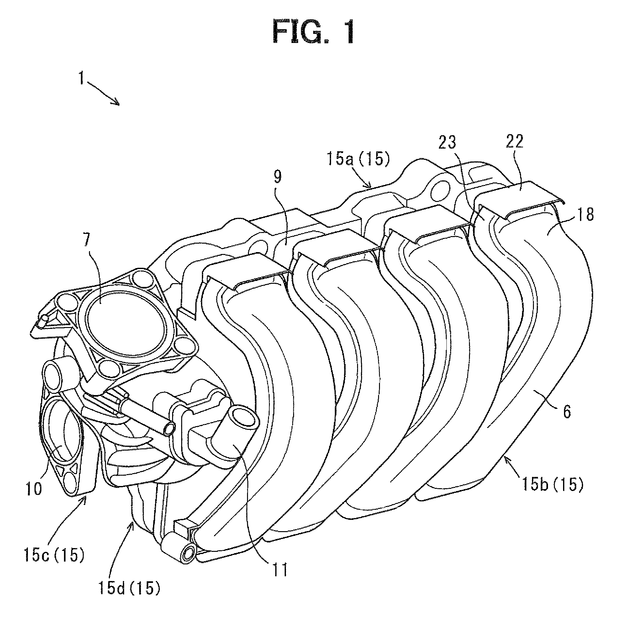
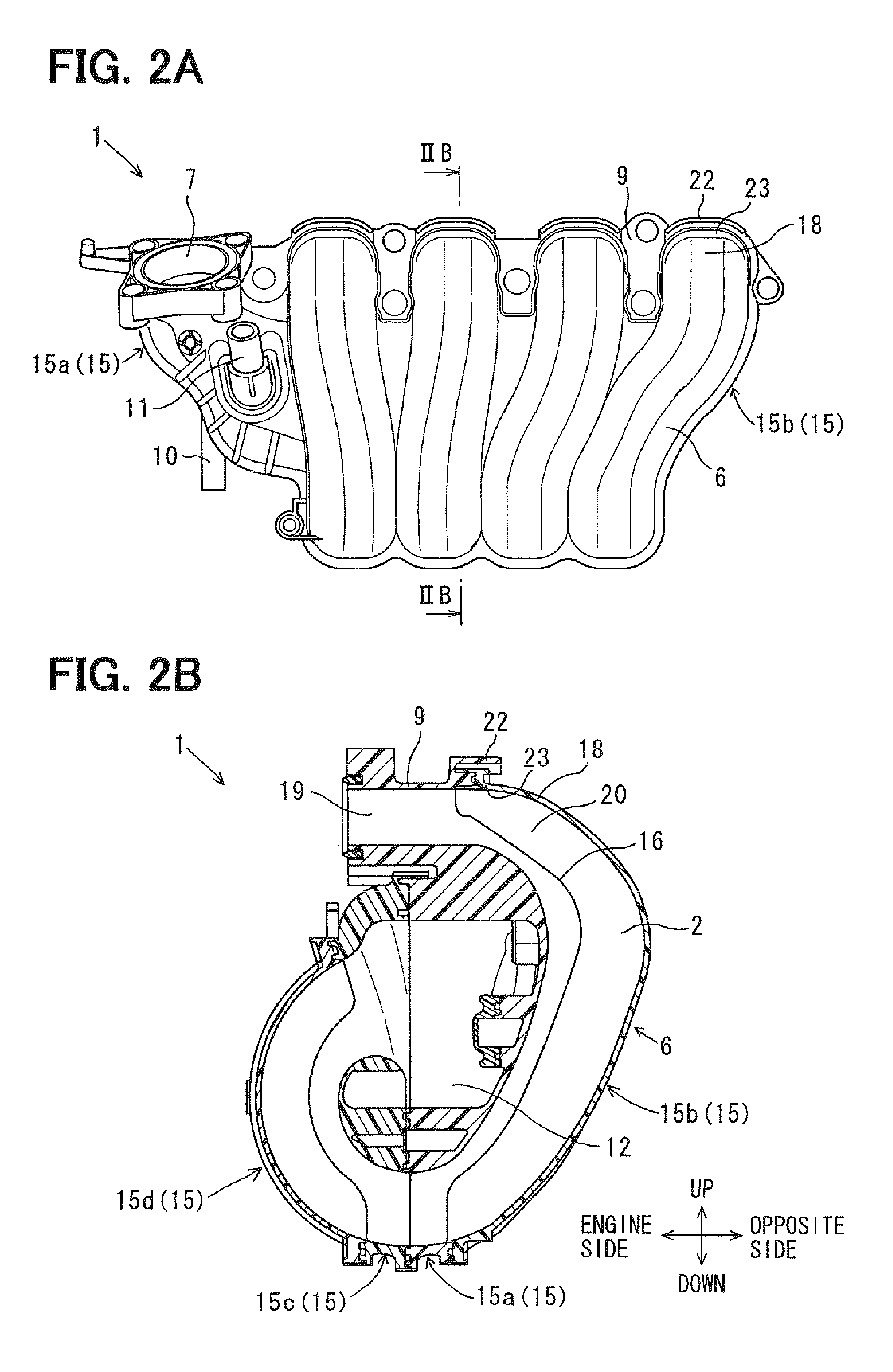
[0026]An intake manifold 1 of an embodiment will be described with reference to FIGS. 1, 2A, 2B, 3, and 4. The intake manifold 1 supplies intake air to a four-cylindered engine 30, which is traversely mounted in an engine compartment of a front engine front drive (FF) type automobile. The engine 30 is arranged in the engine compartment such that cylinders of the engine 30 are arranged in a width direction of the automobile. An engine is typically arranged in this traverse direction in an FF type automobile.

[0027]The intake manifold 1 is mounted to the engine 30 such that intake ports 2 communicating with the cylinders are arranged in the width direction of the automobile. As shown in FIG. 4, a fuel system having an injector 3 and a fuel rail 4 is located above the intake manifold 1. The injector 3 injects fuel toward intake air, and the fuel rail 4 distributes fuel into the injector 3.

[0028]The intake manifold 1 includes a casing 67 an upstream side connector 7, an engine connector ...


PUM

PropertyMeasurementUnit
widthaaaaaaaaaa

Abstract

An intake manifold to be mounted to a traverse engine includes pieces made of resin and welded to each other. The pieces are constructed with a first piece having a connector to be connected to the engine, and a second piece. The second piece has an upper positioning part overlapping with the first piece except for the connector having a linear-shaped outlet passage. The upper positioning part is welded to the first piece so as to define an upstream side passage of the outlet passage. The first piece has a cover, which covers the upper positioning part defining a downstream end of the upstream side passage.

Description

CROSS REFERENCE TO RELATED APPLICATION[0001]This application is based on Japanese Patent Application No. 2008-083561 filed on Mar. 27, 2008, the disclosure of which is incorporated herein by reference in its entirety.BACKGROUND OF THE INVENTION[0002]1. Field of the Invention[0003]The present invention relates to an intake manifold.[0004]2. Description of Related Art[0005]An intake manifold is typically produced by integrating resin-molded pieces. For example, an ultrasonic vibration welding is used for the integrating. FIGS. 5, 6A, 6B, 7, and 8 show an intake manifold 100 for sending intake air into a four-cylindered engine 110. The intake manifold 100 is produced by welding four pieces 101.[0006]Here, a traverse engine is traversely mounted on a front engine front drive (FF) type automobile such that cylinders of the engine are arranged in a width direction of the automobile. In the traverse engine, the intake manifold 100 is disposed such that intake ports 102 communicating with t...

Claims


Application Information

Patent Timeline
Patent Type & Authority Patents(United States)
IPC IPC(8): F02M35/10
CPCF02M35/10144F02M35/10216F02M35/10222F02M35/10321F02M35/10354F02M35/112F02M35/10078
Inventor KAMEDA, YASUTOSHI
Owner DENSO CORP
Why Eureka
Try Eureka