Heat distributing wave tray for a grill

a wave tray and grilling technology, applied in the field of grilling, can solve the problems of uniform panel structure, insufficient radiant and convective heat distribution, and insufficient baffles to address grill specific burner placemen

Active Publication Date: 2011-10-18
WHIRLPOOL CORP
View PDF13 Cites 29 Cited by
  • Summary
  • Abstract
  • Description
  • Claims
  • Application Information

AI Technical Summary

Problems solved by technology

Although such panels improve heat distribution to some extent, the uniform nature of the panels does not address grill specific burner placement.
However, such a baffle is not seen to adequately address the distribution of both radiant and convective heat within the barbecue grill.

Method used


Image

  • Heat distributing wave tray for a grill
  • Heat distributing wave tray for a grill
  • Heat distributing wave tray for a grill

Examples


Embodiment Construction

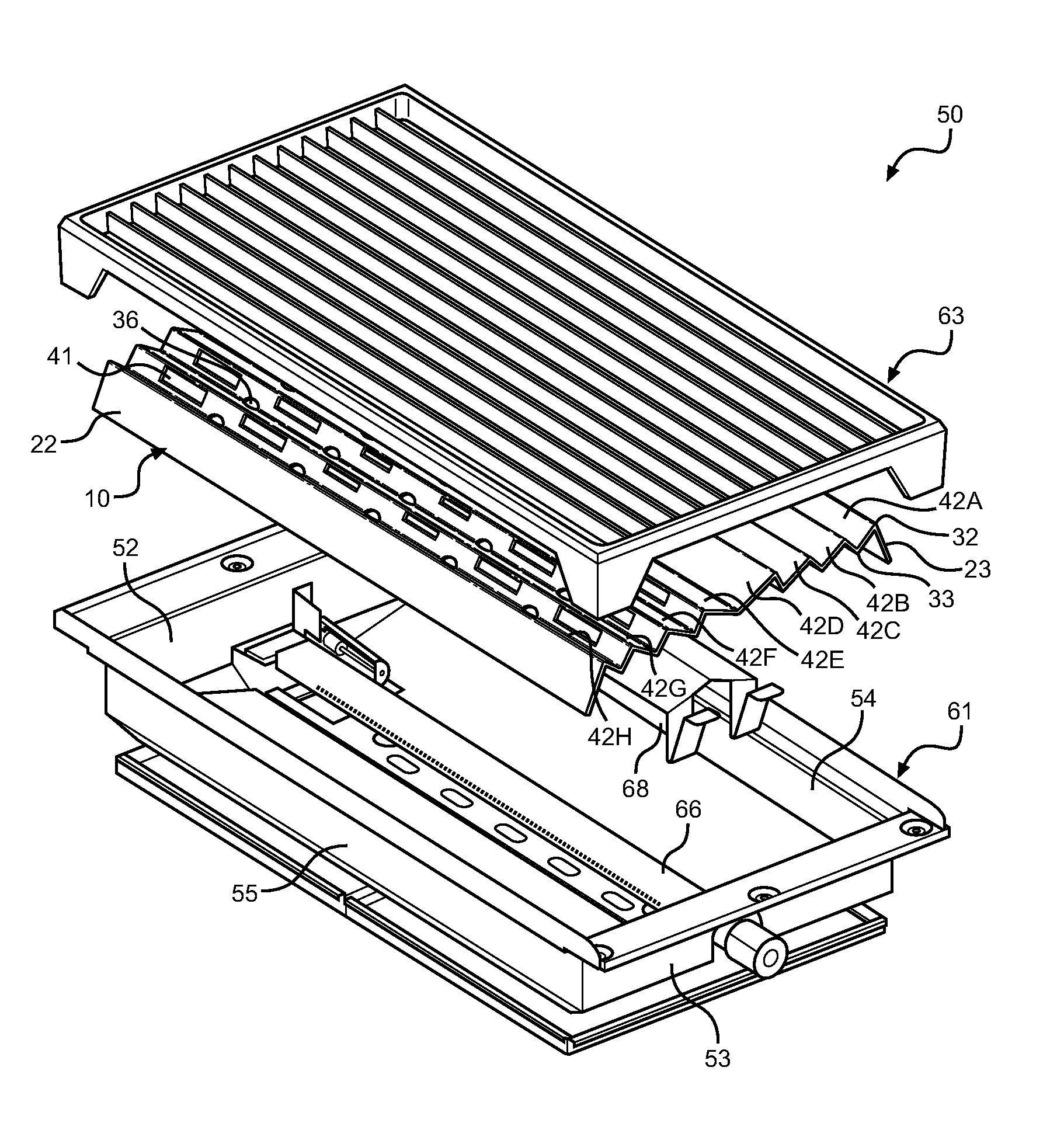
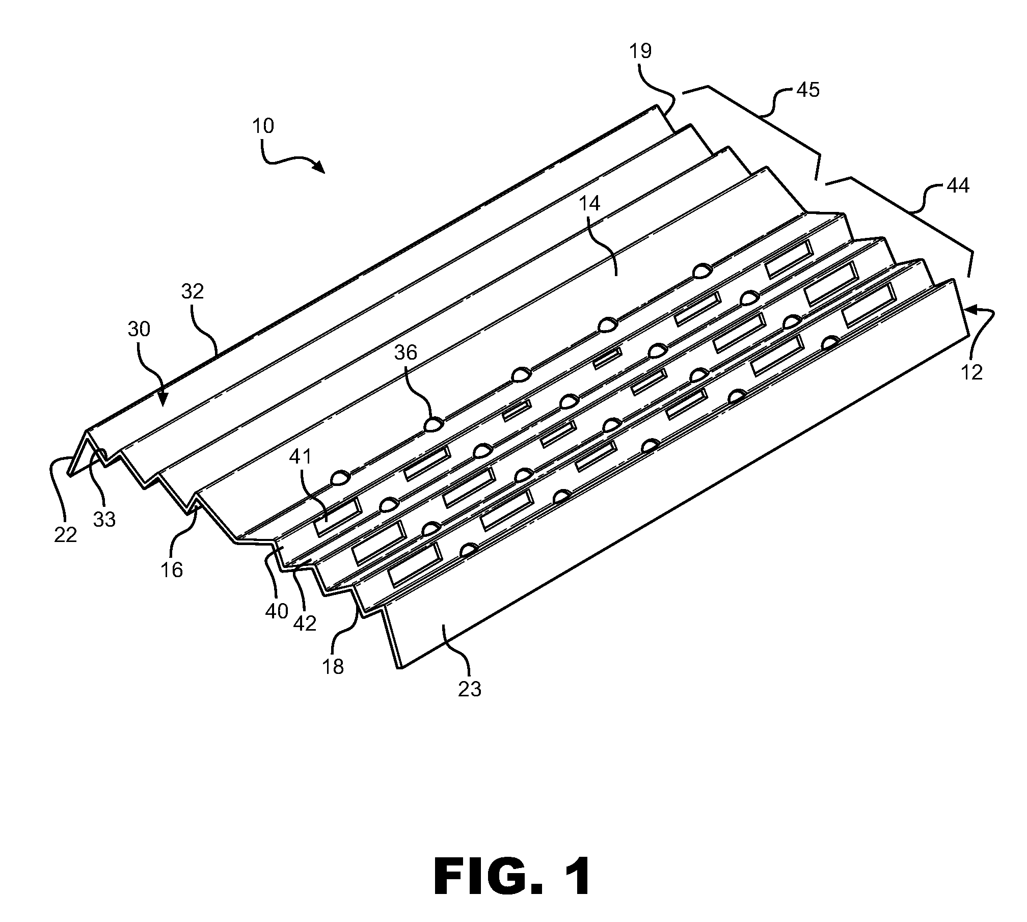
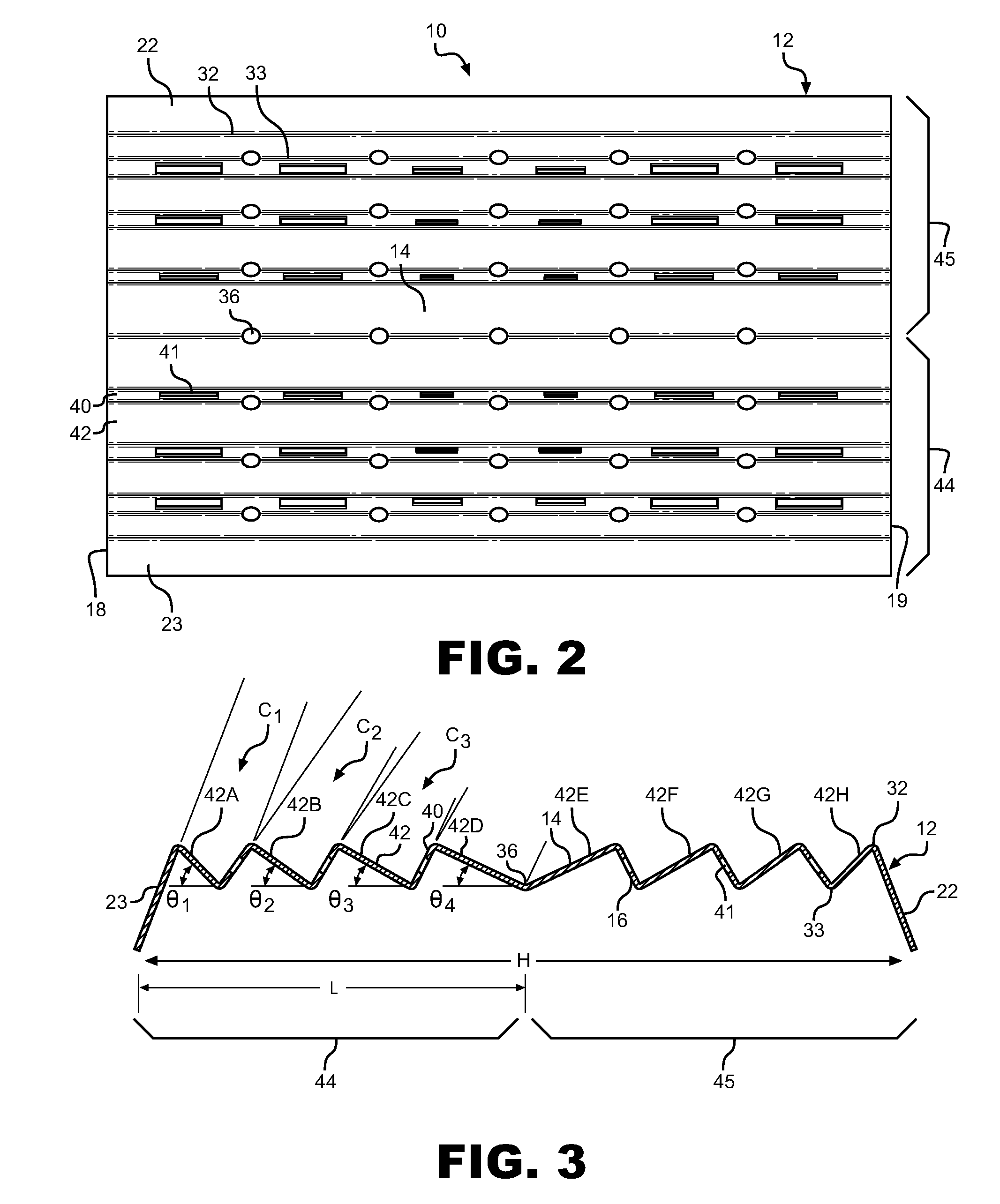
With initial reference to FIGS. 1 and 2, a heat distributing tray constructed in accordance with the present invention is indicated at 10. In general, tray 10 is constituted by a corrugated unitary body 12 of heat conducting material, such as steel. Unitary body 12 includes an upper surface 14, a lower surface 16, first and second, longitudinally spaced opposing side edges 18 and 19, and first and second opposing downwardly extending legs 22 and 23. As shown, legs 22 and 23 extend downwardly from unitary body 12 away from upper surface 14 and provide a means for supporting tray 10. The corrugated structure of unitary body 12 defines a plurality of spaced, substantially parallel channels 30 that extend from first side edge 18 to second side edge 19. In general, channels 30 are defined by respective peaks or crests 32 and troughs 33. A plurality of longitudinally spaced drainage apertures 36 preferably extend through each trough 33 in order to allow any fluids collected on upper surfa...


PUM


Abstract

A heat distributing tray for use in a barbecue grill includes a corrugated unitary body of heat conducting material having alternating solid and grated walls which define channels. More specifically, the body includes first and second side portions defined by both solid walls which extend at gradually decreasing angles with respect to a common horizontal plane and varying length grated walls interconnecting the solid walls. In use, the tray is placed over one or more heating elements in a barbecue housing, with radiant and convective heat from the heating element being optimally distributed throughout the entire interior portion of the barbecue grill due to the relative structure and configuration of the solid walls in relation to the grated walls.

Description

BACKGROUND OF THE INVENTION1. Field of the InventionThe present invention pertains to the art of grilling and, more particularly, to a heat distributing wave tray for grilling, such as on a barbecue grill.2. Description of the Related ArtIn general, gas or electric barbecue grills include one or more tube burners or cooking elements located beneath one or more radiant panels adapted to improve heat distribution across the entire surface of the grill. One example of such an appliance can be seen in U.S. Pat. No. 6,314,871, wherein a plurality of uniform, undulating panels are utilized over a U-shaped burner. Although such panels improve heat distribution to some extent, the uniform nature of the panels does not address grill specific burner placement. One attempt to address the distribution of heat from a specific burner location can be seen in U.S. Pat. No. 5,806,412, which depicts a baffle having holes of various sizes and locations designed to control the combustion gas travel pat...

Claims


Application Information

Patent Timeline
Patent Type & Authority Patents(United States)
IPC IPC(8): F24C3/00F24C3/04A47J37/07A47J27/02F23D14/14
CPCA47J37/0694F23D14/70F23C2203/20
Inventor MURRIN, RYAN S.SELLS, JOEL M.
Owner WHIRLPOOL CORP
Why Eureka
Try Eureka