Engine assembly for aircraft

a technology for aircraft engines and components, applied in machines/engines, liquid fuel engines, transportation and packaging, etc., can solve the problems of less significant longitudinal bending, premature engine wear, and increased friction between the rotating compressor and the turbine blades, so as to reduce the bending

Inactive Publication Date: 2011-10-18
AIRBUS OPERATIONS (SAS)
View PDF8 Cites 9 Cited by
  • Summary
  • Abstract
  • Description
  • Claims
  • Application Information

AI Technical Summary

Benefits of technology

[0020]As a result, with this type of arrangement, the first and second forward engine attachments are very compact, because it is no longer necessary to have a link cooperating with the clevis as was the case in the embodiments of the prior art, since it is now the shear pin which cooperates directly with this same clevis. Thus, other than the gain in terms of compactness of the forward attachments, gains are also achieved in terms of mass and cost.
[0021]Moreover, the pin therefore goes through the two walls of the clevis which are located away from each other, in the transverse direction. The shear pin is therefore solicited by two loads in opposite directions at the level of its two distinct points cooperating with the walls of the clevis, respectively, which makes it possible to obtain balancing of the pin advantageously translating to a considerable decrease of the bending effect previously encountered with the shear pin solicited in a single point by the link of the clevis / link assembly.
[0022]Preferably, the engine assembly also comprises a ball joint having a casing fixed on the fan case, and a ball-joint yoke supporting the shear pin. With this type of configuration, the pin mechanically solicited in bending advantageously transmits almost no stress to the fan case, since in this case, it is the ball-joint yoke integral with the shear pin which will move in its associated casing, built into the case. The presence of the abovementioned ball joint therefore implies that the fan case is substantially protected from the harmful effects likely to be caused by the bending of the shear pin mechanically connected to this same case.
[0023]Still preferably, the shear pin is mounted slidingly in the ball-joint yoke. This type of assembly has the advantage of allowing relative movement between the pin and the ball-joint yoke in a direction defined by the axis of the pin. This is particularly interesting in the sense that the engine can then be deformed without undergoing overstresses at the level of its area connected with the shear pin able to slide in the ball joint. For information, this specificity is in particular very advantageous during the elongation phases of the engine, which cause a non-negligible separation clearance between the fan case and the clevis of each side forward engine attachment.
[0026]Preferably, the first and second engine attachments are passed through by a plane defined by the longitudinal axis of the turbojet engine and a transverse direction thereof. Thus, since loads are transferred at the axis of the turbojet engine, the longitudinal bending of the latter part is advantageously considerably decreased.

Problems solved by technology

In a manner known by one skilled in the art, despite the presence of the thrust mount device, these thrust loads generated by the engine typically cause more or less significant longitudinal bending of said engine, i.e. bending resulting from a torque exerted in a transverse direction of the aircraft.
When this type of longitudinal bending occurs, in particular during the cruising phases of the aircraft, one then encounters increased friction between the rotating compressor and turbine blades, and the central fan case of the engine.
The main consequence of the friction encountered resides in premature wear of the engine, which is naturally harmful for the lifespan of this engine, as well as for its performance.
Thus, this particular arrangement of the engine attachments leads to a considerable decrease in the bending encountered at the level of the central case, whether this bending is due to the thrust loads generated by the turbojet engine, or due to the gusts likely to be encountered during the various phases of flight of the aircraft.
As a result, the aforementioned decrease in bending creates a significant drop in the friction between the rotating compressor and turbine blades and the central engine case, and therefore greatly limits the losses of output due to wearing of these blades.
Nevertheless, it must be noted that to date, no design has shown itself to be totally satisfactory for the first and second forward engine attachments, called side forward attachments.
Indeed, the problems encountered in the known solutions are essentially made first of the significant bulk of these attachments, in particular due to the use of a clevis / link type assembly, and secondly of the presence of a very significant bending phenomenon at the level of a shear pin oriented transversely and mounted on the fan case of the turbojet engine, as well as on said link of the assembly.

Method used


Image

  • Engine assembly for aircraft
  • Engine assembly for aircraft
  • Engine assembly for aircraft

Examples


Embodiment Construction

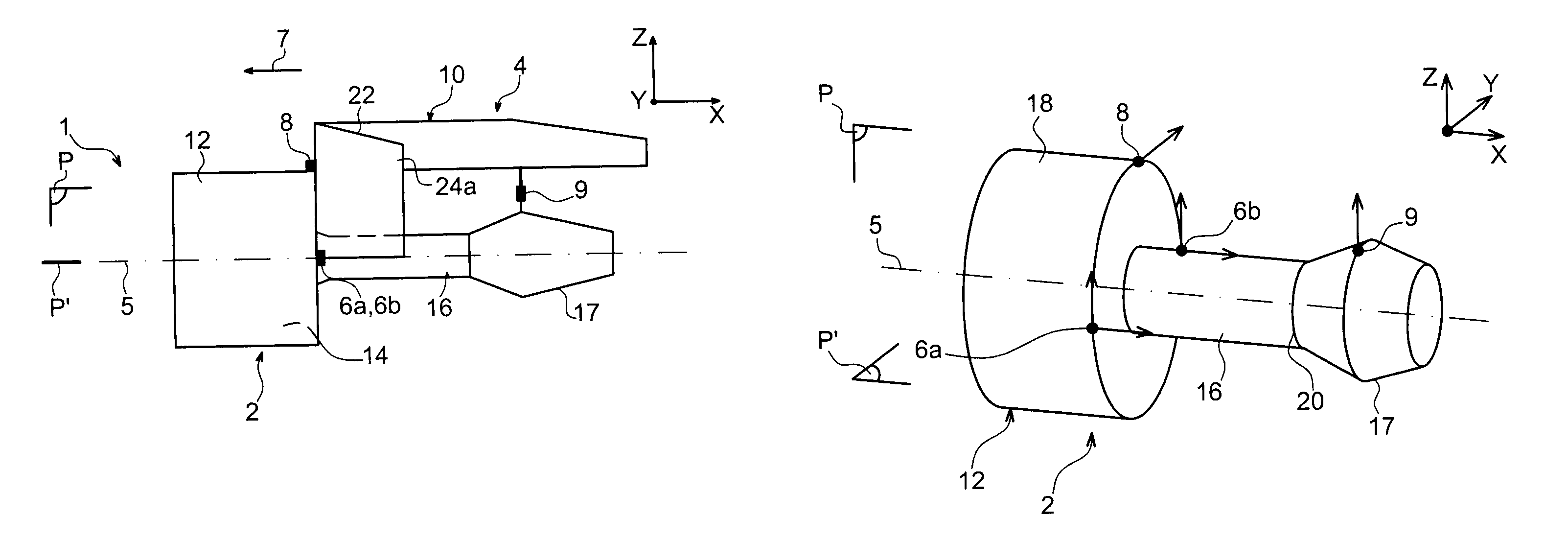
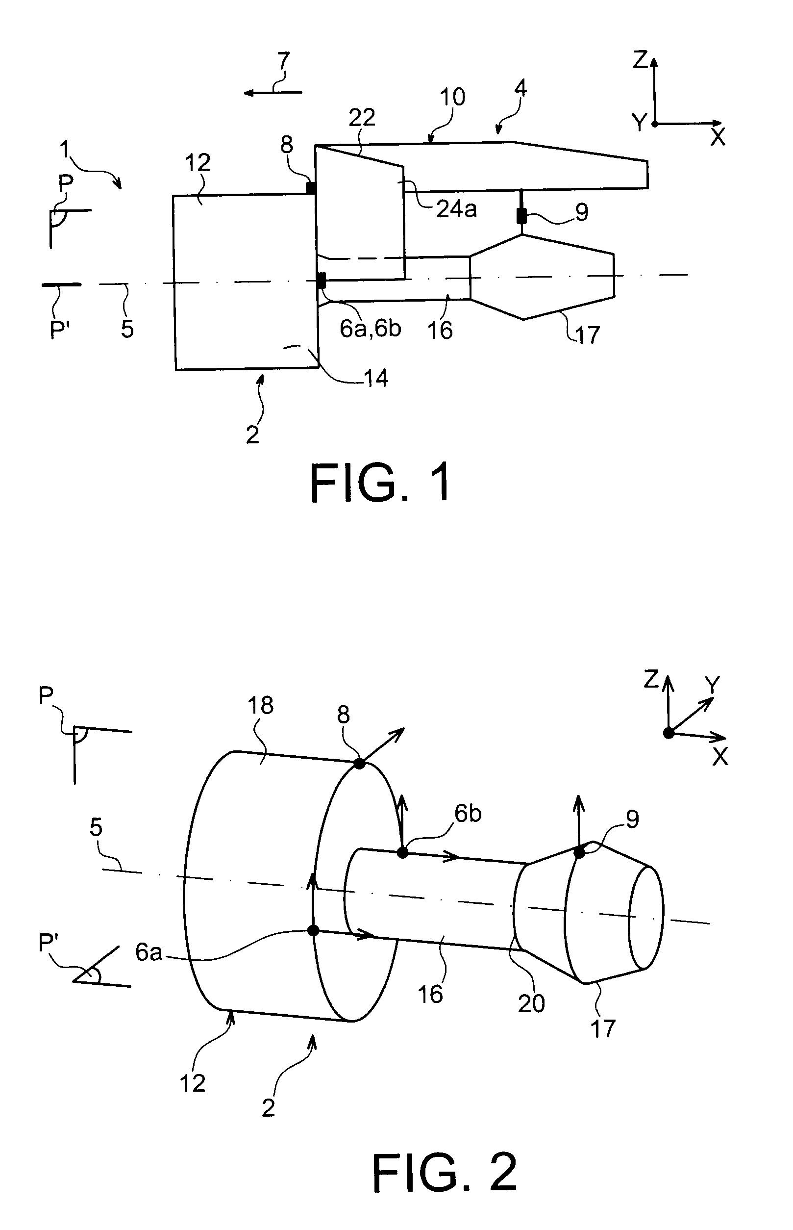
[0037]In reference to FIG. 1, one sees an aircraft engine assembly 1 according to a first preferred embodiment of the present invention, this assembly 1 being designed to be fixed under a wing of the aircraft (not illustrated).

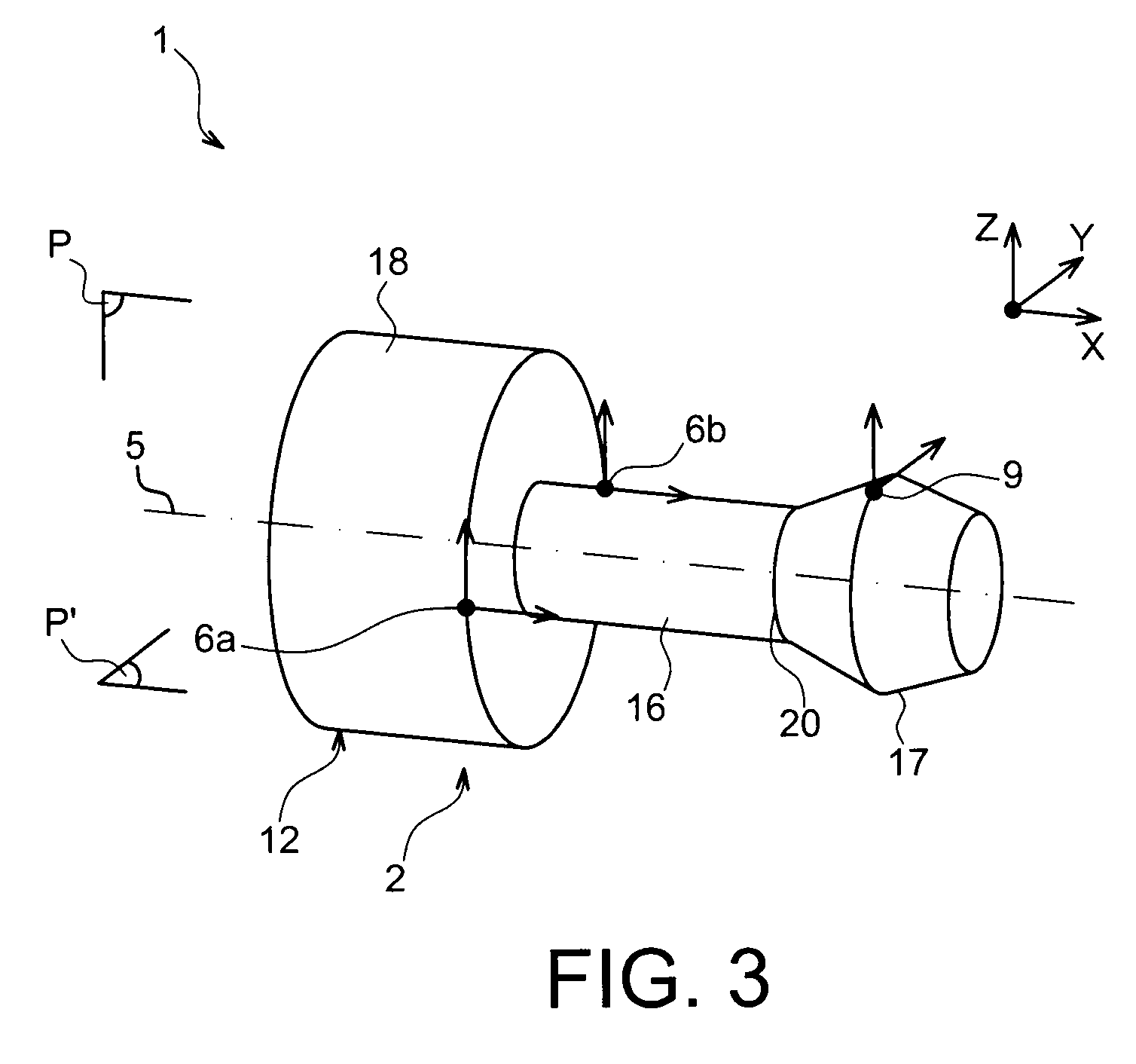
[0038]Globally, the engine assembly 1 comprises a turbojet engine 2, an engine mount 4, as well as a plurality of engine attachments 6a, 6b, 8, 9 ensuring fixing of the turbojet engine 2 under this engine mount 4 (attachment 6b being concealed by attachment 6a in this FIG. 1). For information, it is noted that the assembly 1 is designed to be surrounded by a nacelle (not shown) and that the engine mount 4 comprises another series of attachments (not shown) making it possible to ensure the suspension of this assembly 1 under the wing of the aircraft.

[0039]In the remainder of the description, by convention, X designates the direction parallel to a longitudinal axis 5 of the turbojet engine 2, Y the direction oriented transversely in relation to this same turboje...


PUM


Abstract

An aircraft engine assembly including a turbojet engine, an engine mount, and a plurality of engine attachments. The engine attachments include first and second forward attachments fixed to a fan case and located symmetrically in relation to a plane defined by a longitudinal axis of the turbojet engine and a vertical direction thereof, both forward attachments configured to transfer loads exerted in a longitudinal direction of the turbojet engine and in the vertical direction thereof. Moreover, each of the two forward attachments includes a shear pin mounted on the case and going through two walls of a clevis fixed on the engine mount.

Description

TECHNICAL FIELD[0001]The present invention relates generally to an aircraft engine assembly, of the type comprising a turbojet engine, a securing pylon and a plurality of engine attachments inserted between this securing pylon and the turbojet engine.PRIOR ART[0002]In a known manner, the security pylon of this type of engine is provided to form a connecting interface between an engine, of the turbojet engine type, and an aircraft wing equipped with this assembly. It allows the loads generated by its associated turbojet engine to be transmitted to the airframe, and also provides a path for fuel lines, electric and hydraulic systems, and air between the engine and the aircraft.[0003]To ensure load transmission, the engine mount comprises a rigid structure, for example of <<box>> type, i.e. formed by the assembly of spars and of side panels joined together via transverse ribs.[0004]A mounting system is inserted between the engine and the rigid structure of the engine mount,...

Claims


Application Information

Patent Timeline
Patent Type & Authority Patents(United States)
IPC IPC(8): B64D27/00
CPCB64D27/26B64D2027/264B64D2027/266
Inventor DIOCHON, LIONELCETOUT, JEAN-MICHELLAFONT, LAURENT
Owner AIRBUS OPERATIONS (SAS)
Why Eureka
Try Eureka